• Tired of adverts on RWI? - Subscribe by clicking HERE and PMing Trailboss for instructions and they will magically go away!

Dogwood's Watchmaking Journey

KJ2020

Time Traveler
Supporter
12/3/18
35,657
71,278
113
Great info. I only have 5 minute epoxy on my bench, but 30 minute would be easy to acquire. I also have UV epoxy which might be even easier to use. Do you remove the old shellac before repairing? Or leave it in place?
Remove it completely from the bad stone. You can leave the good one as is. You could get away with 5 minute epoxy. Remember you have infinite do-overs, haha.
 
Last edited:
  • Like
Reactions: dogwood

dogwood

I'm Pretty Popular
Patron
Section Moderator
Certified
7/9/21
2,441
5,420
113
Canada
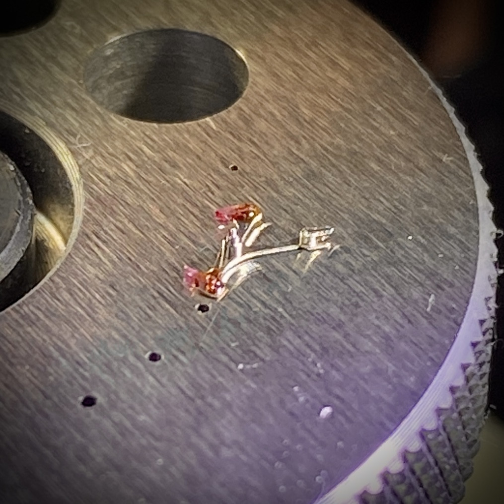
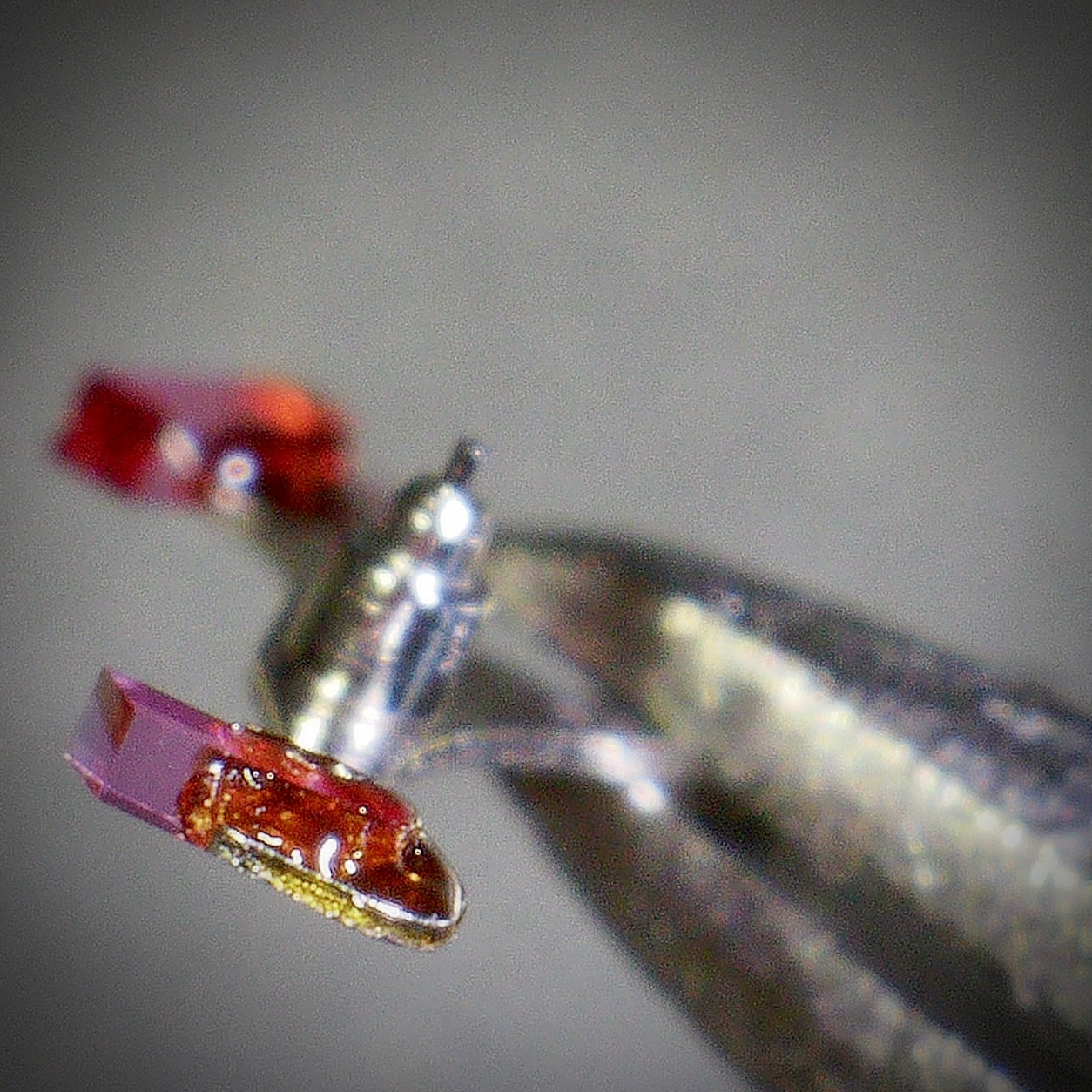
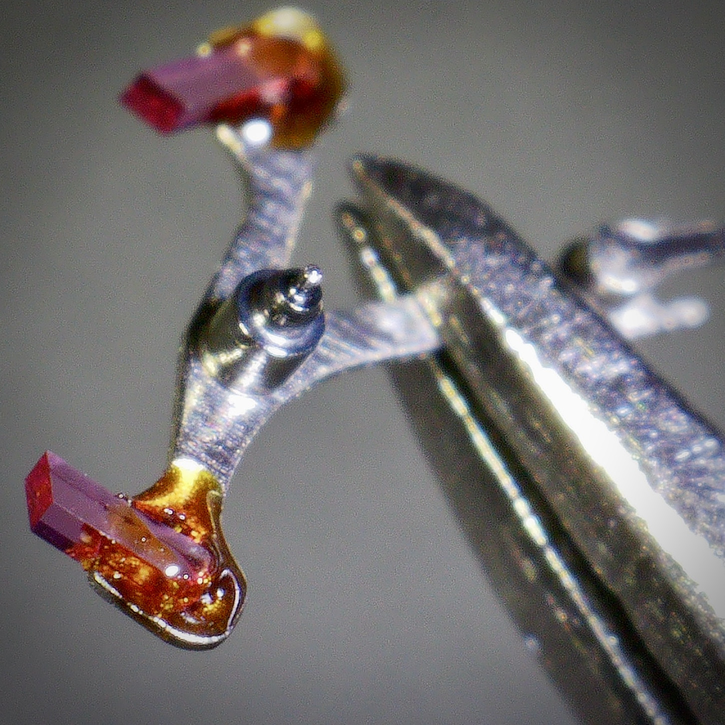
Follow-up on the repair of the VS3235 pallet fork. I followed KJ2020's advice and used a staking plate as a jig for the pallet fork to lie flat on while I did the repair. I picked a hole in the plate that was just large enough for the pallet fork's top pivot. The flat plate was a nice way to align the pallet fork stone that was loose into the position it needed to be in.


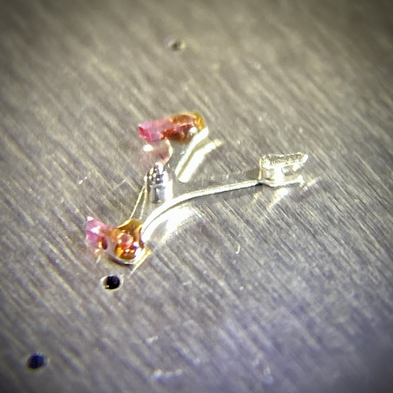
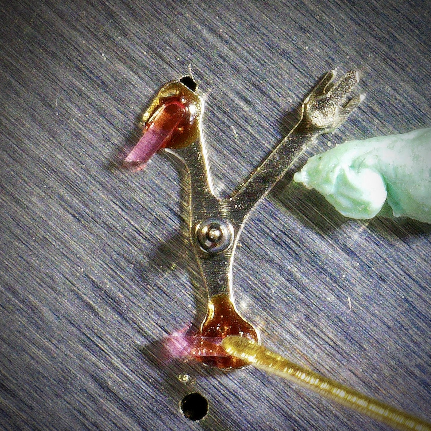
I decided to try using UV glue rather than the 5-minute epoxy I had on hand. I figured it would be a little easier to work with since I wouldn't be under any time pressure (a good thing when doing something for the first time). I used an old oiler and dabbed on the UV glue. I used a tiny piece of rodico to try to hold the pallet fork in place while I dabbed on the glue, since even though the UV glue wasn't curing, it was still sticky because it was wet and the pallet fork doesn't have much mass to stay put on its own. Although you can see the pallet fork came loose from the rodico anyway.


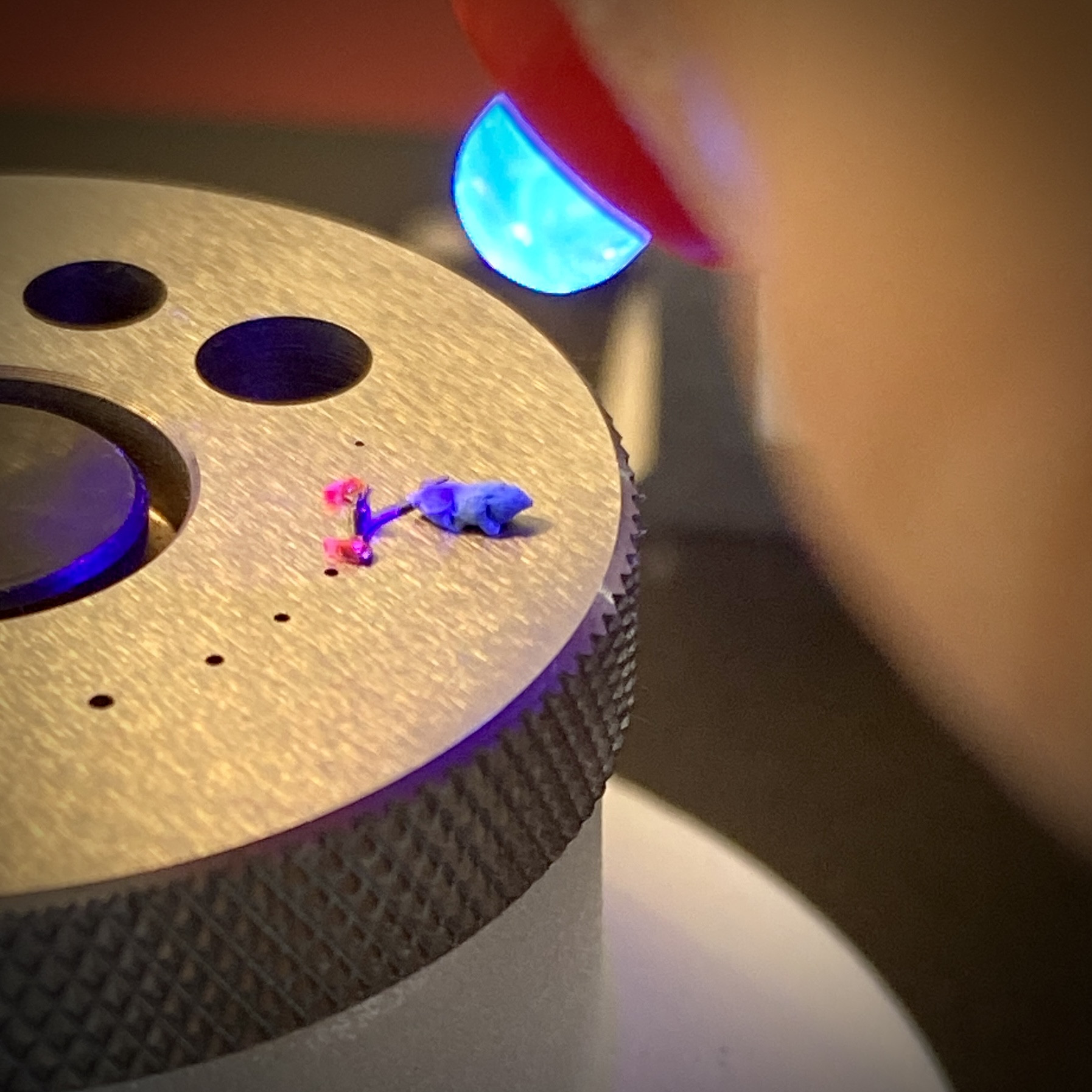
Then it was a quick blast with the UV death ray to get the glue to harden.


I'm happy with how this came out. I haven't tested it in a movement yet (I'm going to wait an hour or so for the UV glue to fully set before I install it). But it certainly looks like the stone is back where it needs to be.


dogwood

I'm Pretty Popular
Patron
Section Moderator
Certified
7/9/21
2,441
5,420
113
Canada
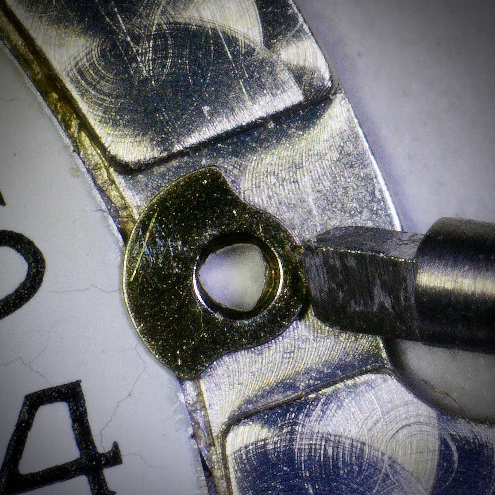
Something I find quite annoying about the VS3235 and VR3235 movements is the swivel clip they employ to secure the date wheel.


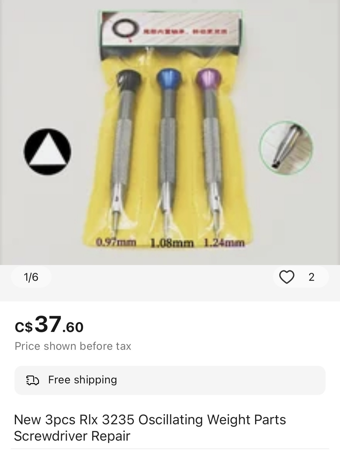
This clip has an unusual triangular socket head that requires a bespoke tool, not unlike how the 32-series Rolex movement rotors are secured using a proprietary triangular socket head screw. I recently saw a set of three triangular head screw drivers on AliExpress and decided to buy them to see if any would be suitable for the date wheel swivel clip.


Even though the stated sizes of these screw drivers were too large, I was hopeful that the size labels were incorrect and one of the screw drivers would fit. I was wrong. They were all too big. Worse, none of them fit the rotor screw either.


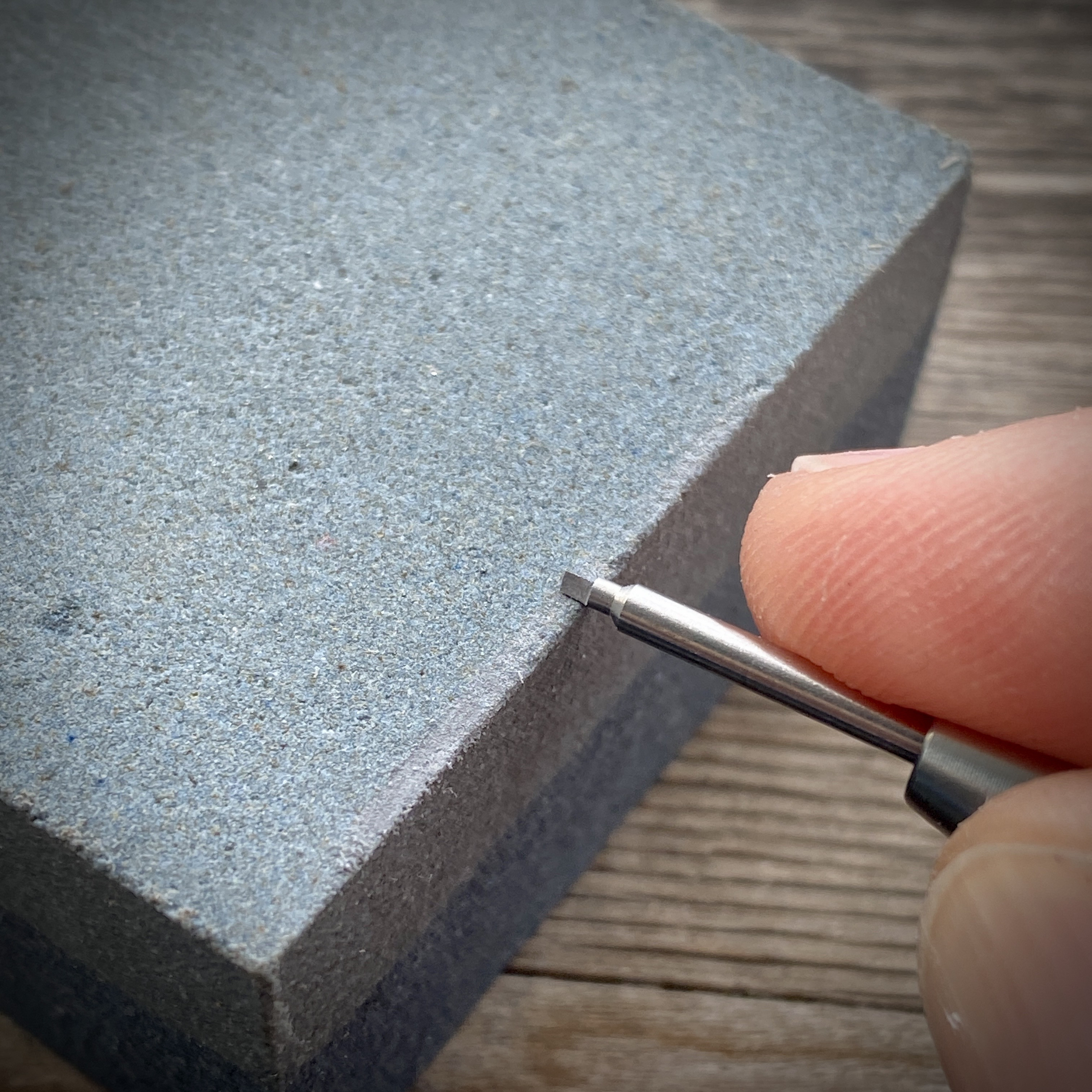
But I figured since I had three useless triangular screw drivers, I could simply stone one of them down to size.


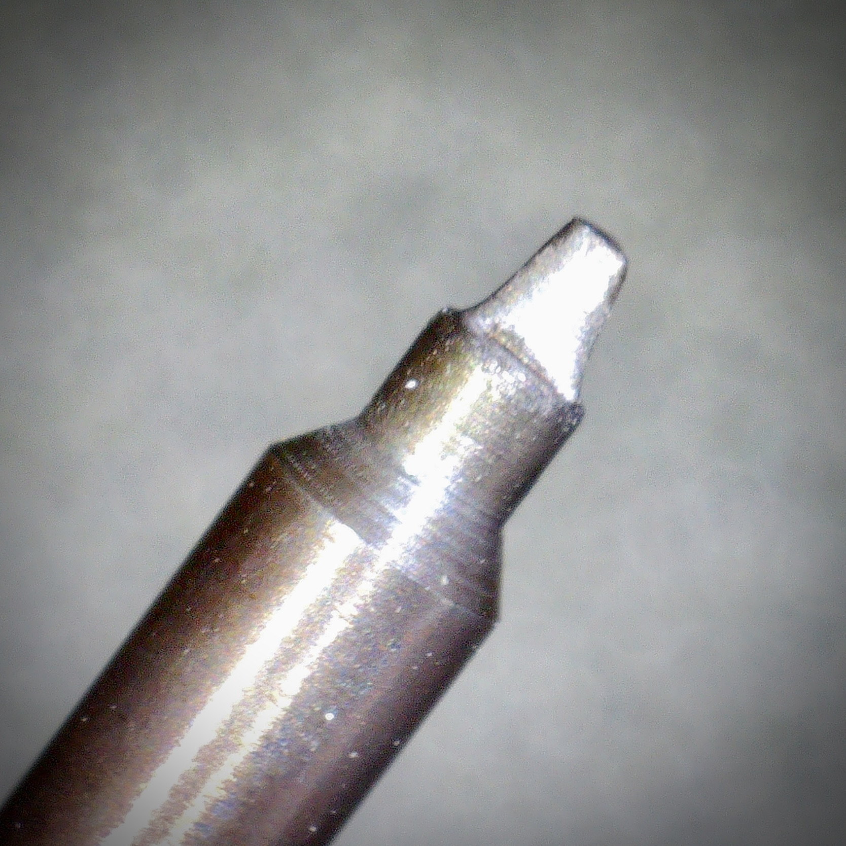
After sneaking up on the dimensions, I had a tool that worked. However, the steel of the tip was exceptionally soft and I managed to round the tool on a swivel clip on an old parts movement that I’d previously abused with a 0.6mm screw driver.

I was able to reshape the tool with the stone, but wanted to try hardening the steel. I don’t know what kind of steel the tip is but hopefully it’s a high enough carbon alloy that I can harden it by heating and quenching it. I don’t have a blow torch, so I just used a lighter flame. I managed to get the tip glowing red before dunking it in water. I think it’s harder now, when I tested it with a file it’s quite hard to get the file to mark it compared to before.


If anyone knows where I can buy a better tool for this swivel clip, please let me know.
 

CTbeforeLP

I'm Pretty Popular
Patron
Certified
25/12/21
1,087
1,352
113
Canada
Something I find quite annoying about the VS3235 and VR3235 movements is the swivel clip they employ to secure the date wheel.


This clip has an unusual triangular socket head that requires a bespoke tool, not unlike how the 32-series Rolex movement rotors are secured using a proprietary triangular socket head screw. I recently saw a set of three triangular head screw drivers on AliExpress and decided to buy them to see if any would be suitable for the date wheel swivel clip.


Even though the stated sizes of these screw drivers were too large, I was hopeful that the size labels were incorrect and one of the screw drivers would fit. I was wrong. They were all too big. Worse, none of them fit the rotor screw either.


But I figured since I had three useless triangular screw drivers, I could simply stone one of them down to size.


After sneaking up on the dimensions, I had a tool that worked. However, the steel of the tip was exceptionally soft and I managed to round the tool on a swivel clip on an old parts movement that I’d previously abused with a 0.6mm screw driver.

I was able to reshape the tool with the stone, but wanted to try hardening the steel. I don’t know what kind of steel the tip is but hopefully it’s a high enough carbon alloy that I can harden it by heating and quenching it. I don’t have a blow torch, so I just used a lighter flame. I managed to get the tip glowing red before dunking it in water. I think it’s harder now, when I tested it with a file it’s quite hard to get the file to mark it compared to before.


If anyone knows where I can buy a better tool for this swivel clip, please let me know.


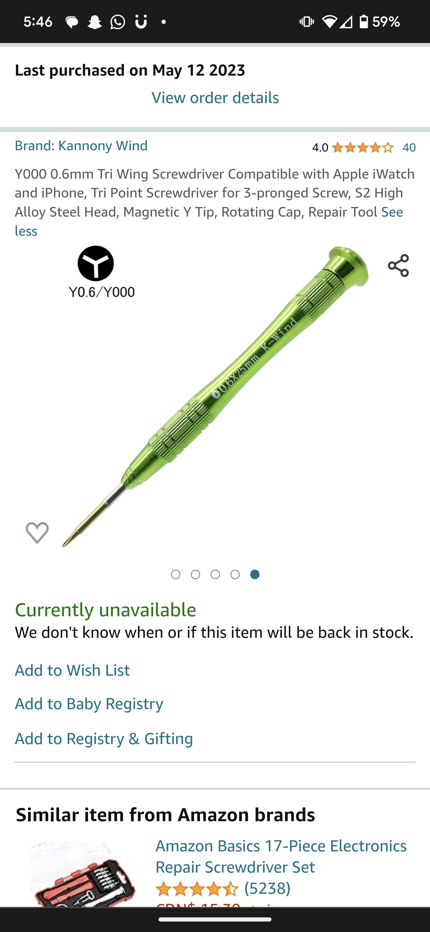
I have been using this screwdriver off of Amazon. Works great. BUT I'm not sure if the tip fits exactly into the triangular slot in that swivel...


  • Like
Reactions: Itto and dogwood

dogwood

I'm Pretty Popular
Patron
Section Moderator
Certified
7/9/21
2,441
5,420
113
Canada
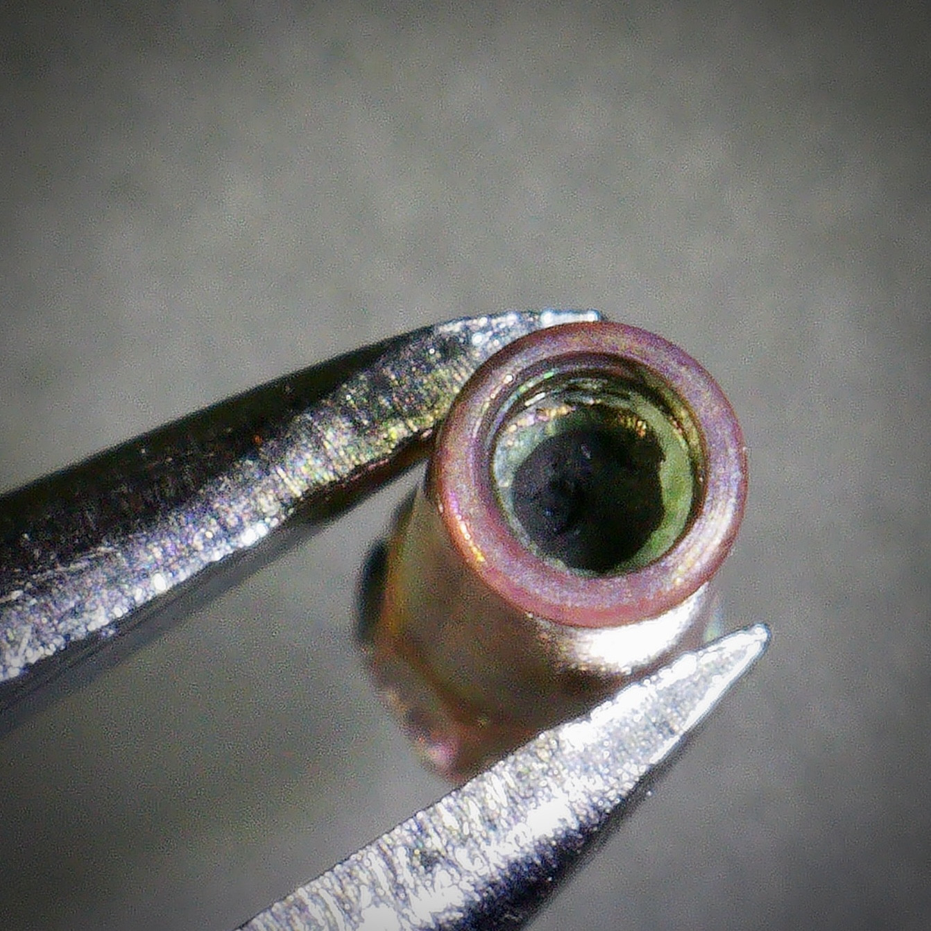
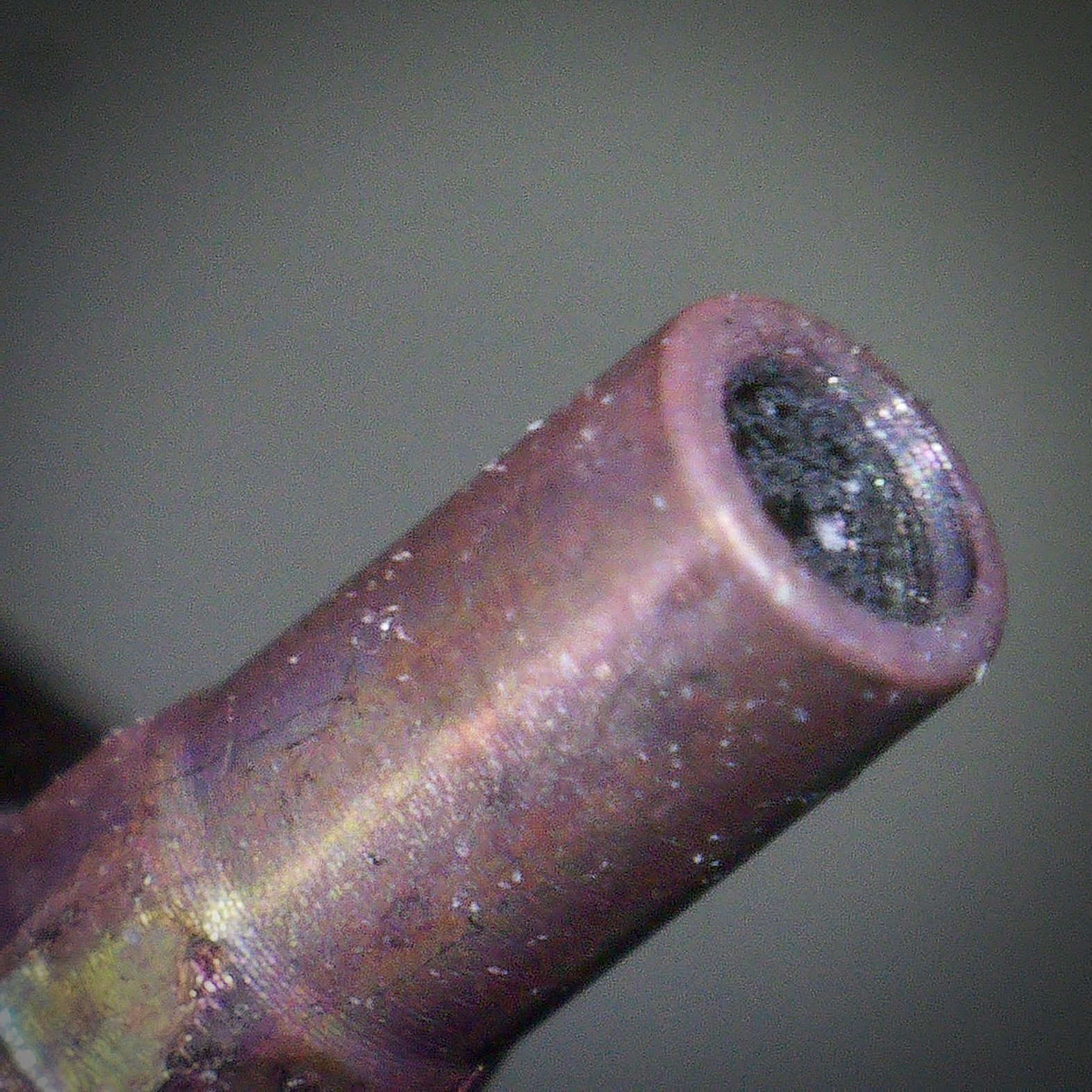
Conclusion of the crown plunger & broken stem saga. I soaked the parts in alum solution at 60-65C for about two days with the occasional blast of one minute of ultrasonic cleaner. In the end the stem did dissolve / rust away. But it’s worth noting that this process is a balancing act — the alum solution attacks both metals, it will just erode away the steel of the stem faster than it will be able to dissolve the metal of the crown plunger sleeve. You can see that the surface of my crown plunger sleeve is tarnished from the exposure to the harsh solution. But I did manage to remove the broken stem, so I’m gonna call this a win.


dogwood

I'm Pretty Popular
Patron
Section Moderator
Certified
7/9/21
2,441
5,420
113
Canada
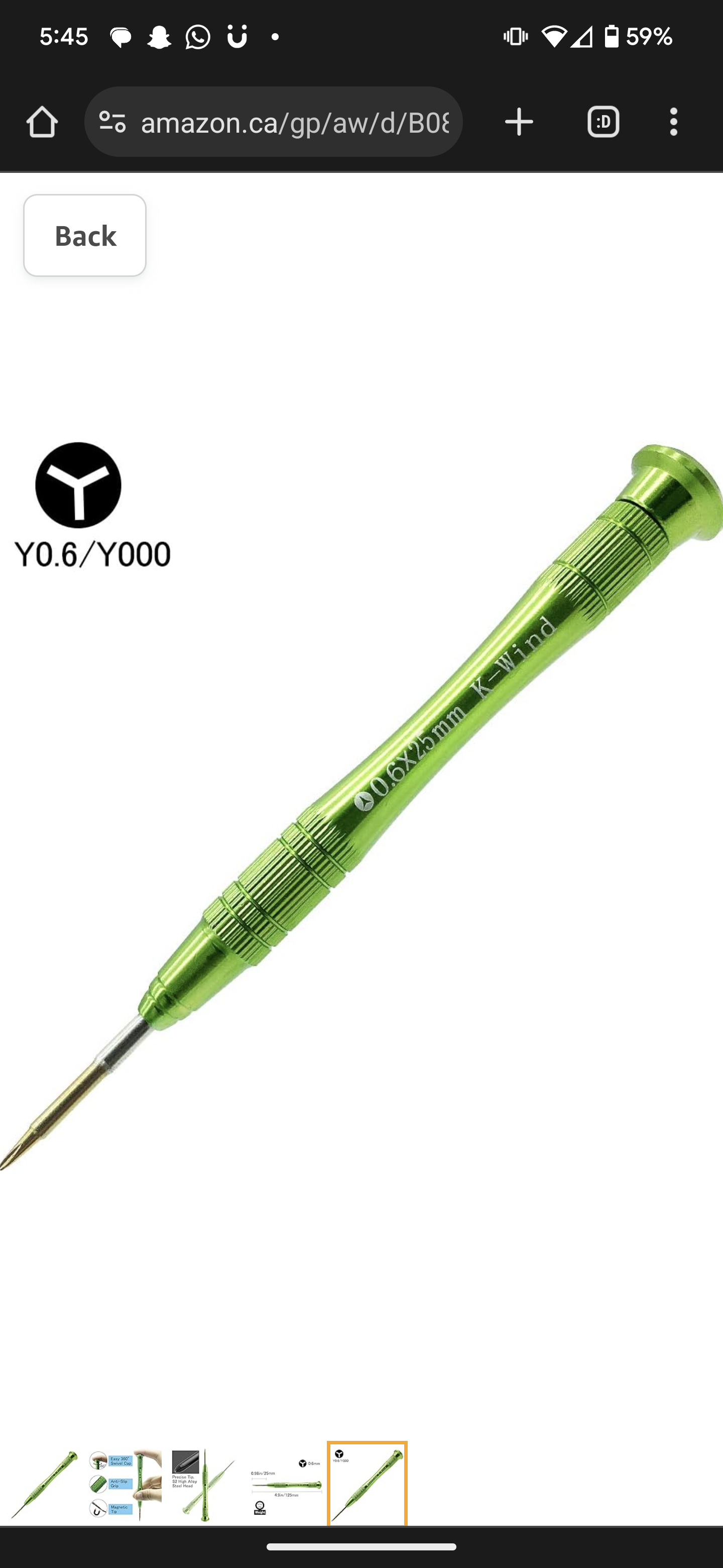
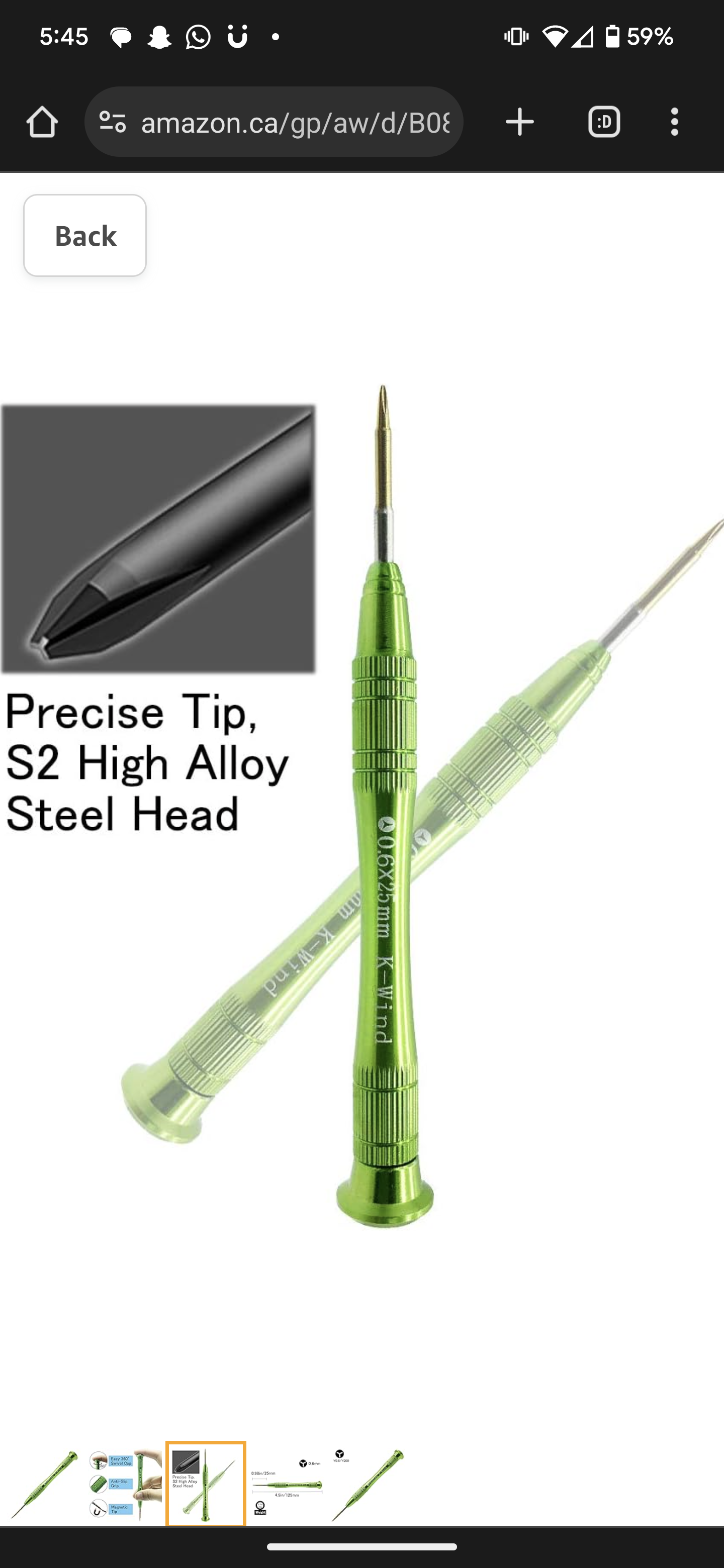
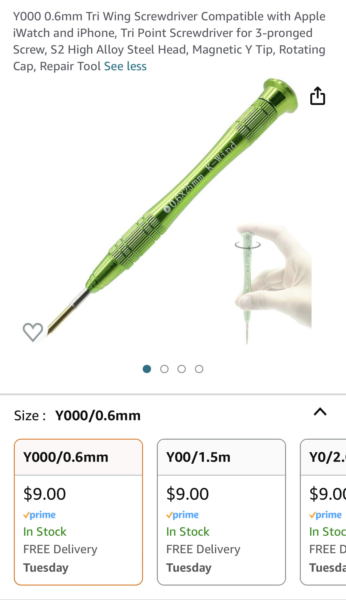
I ended up buying the tool that @CTbeforeLP recommended for rotating the date disc retaining clip on VS3235 and VR3235 movements. It appears to be a tool that’s required for removing some proprietary screw on an iPhone which is good news because it means it’s a mass produced tool that’s cheap and available everywhere. Mine cost $9 CAD including next day delivery.


Here’s the link:


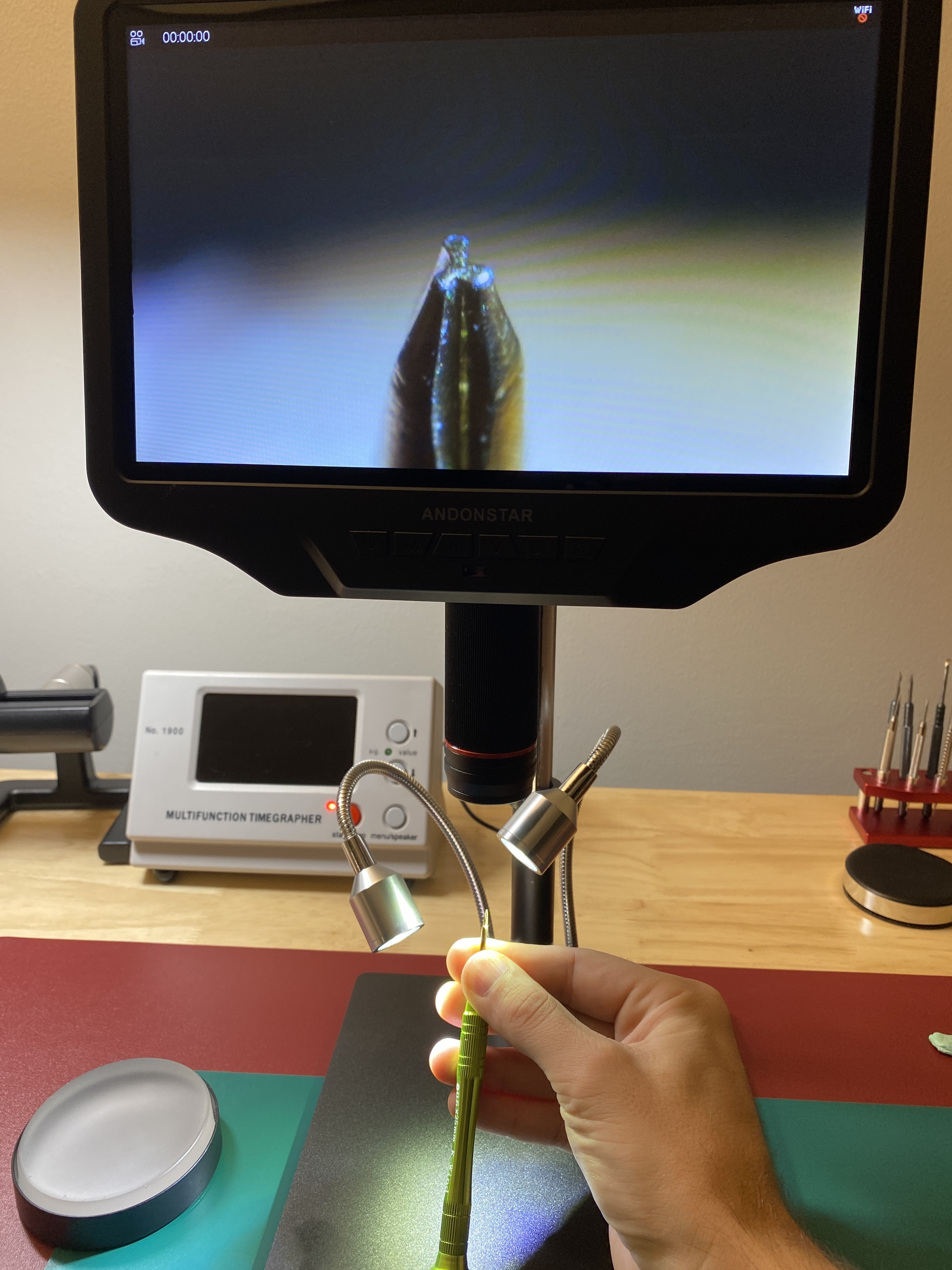
The tip appears to by a ~0.6mm Y-shape. And after testing it, it appears to work on the date wheel retaining clip. I’m not sure how durable it will be, but it’s nice to have a tool that’s better than a 0.6mm flat head screw driver.


  • Like
Reactions: Itto and CTbeforeLP

dogwood

I'm Pretty Popular
Patron
Section Moderator
Certified
7/9/21
2,441
5,420
113
Canada
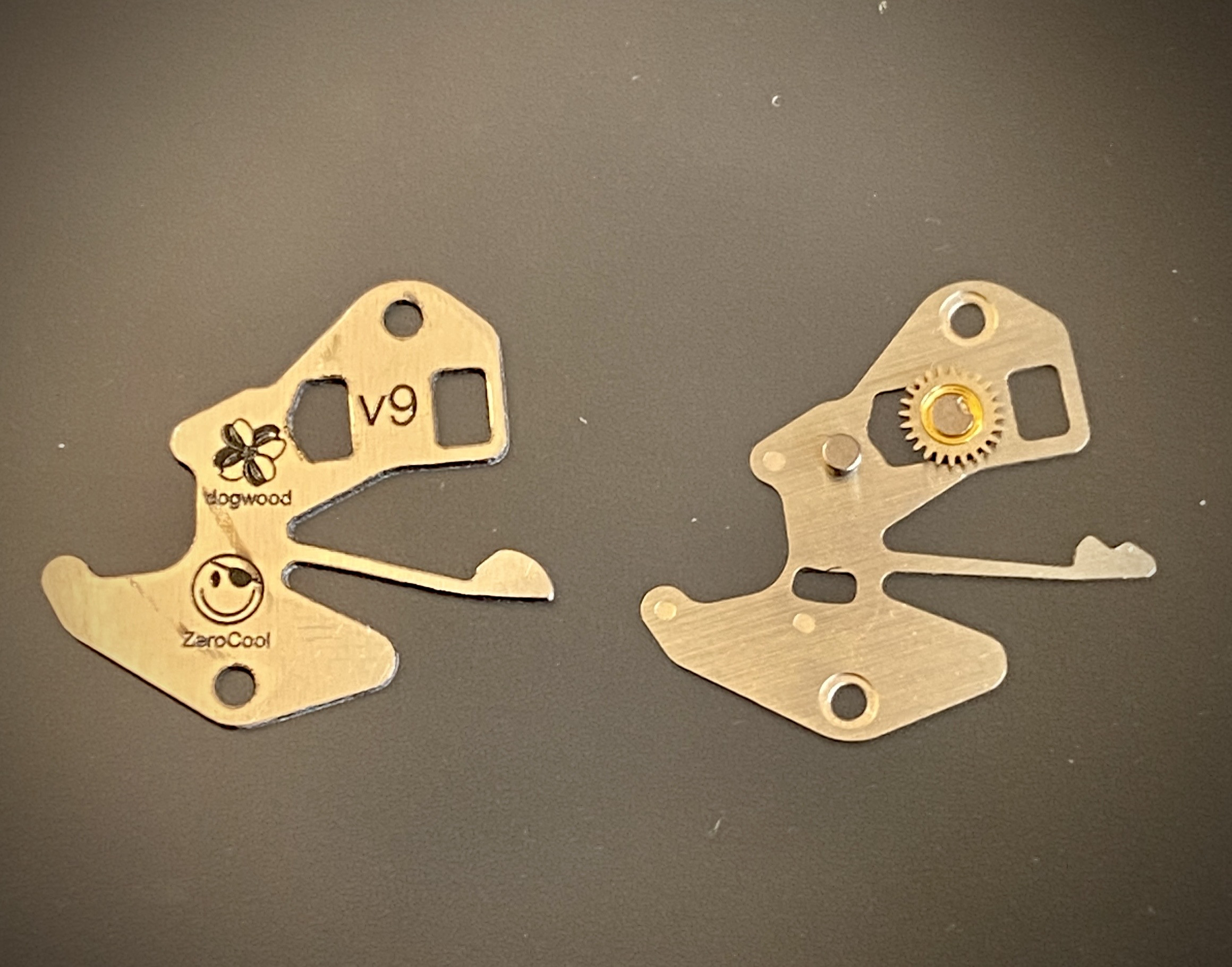
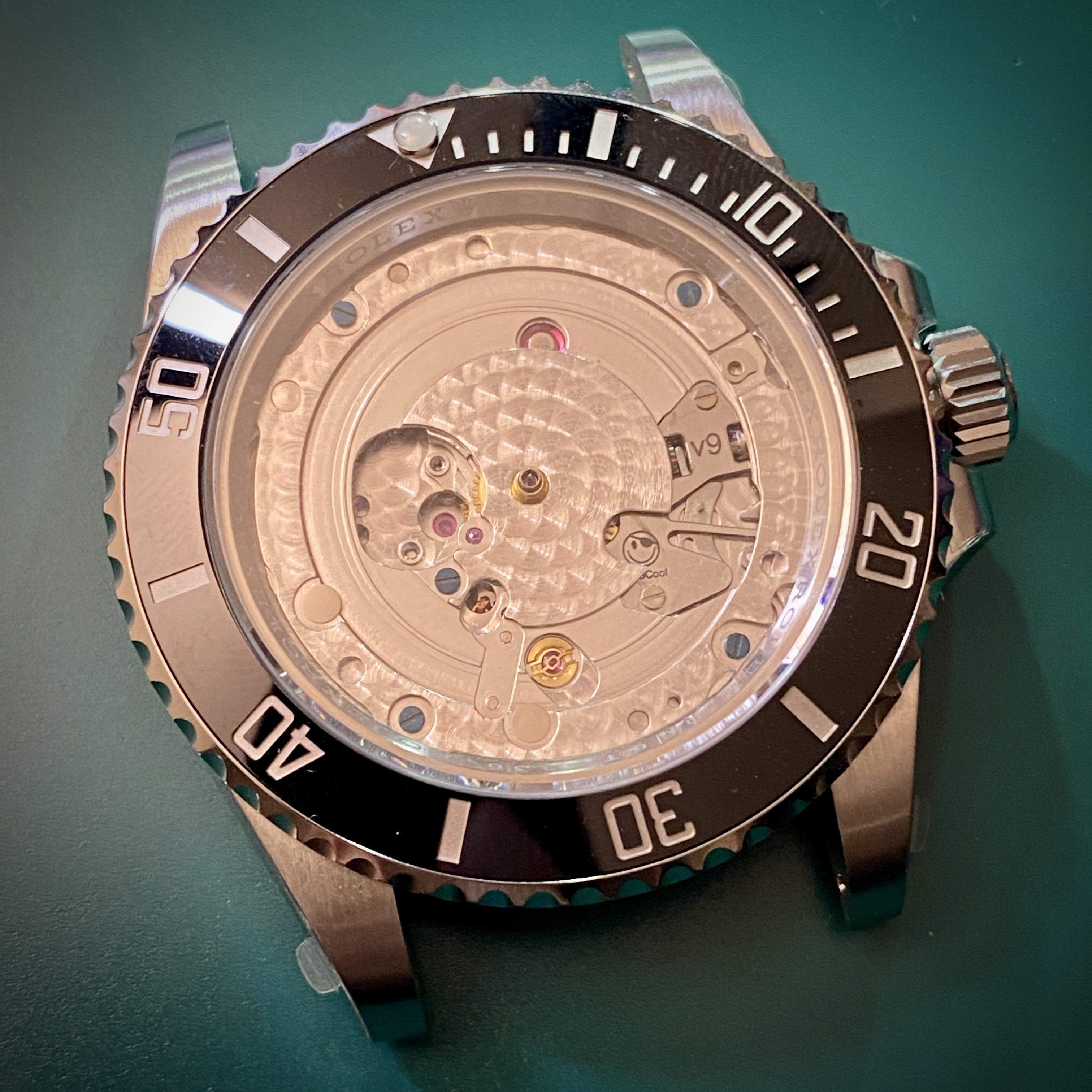
I had my first chance to install one of the new 3230-231 setting lever springs into a VSF 124060 no-date submariner today that @CTbeforeLP had sent to me to service and to install the modded setting lever spring.


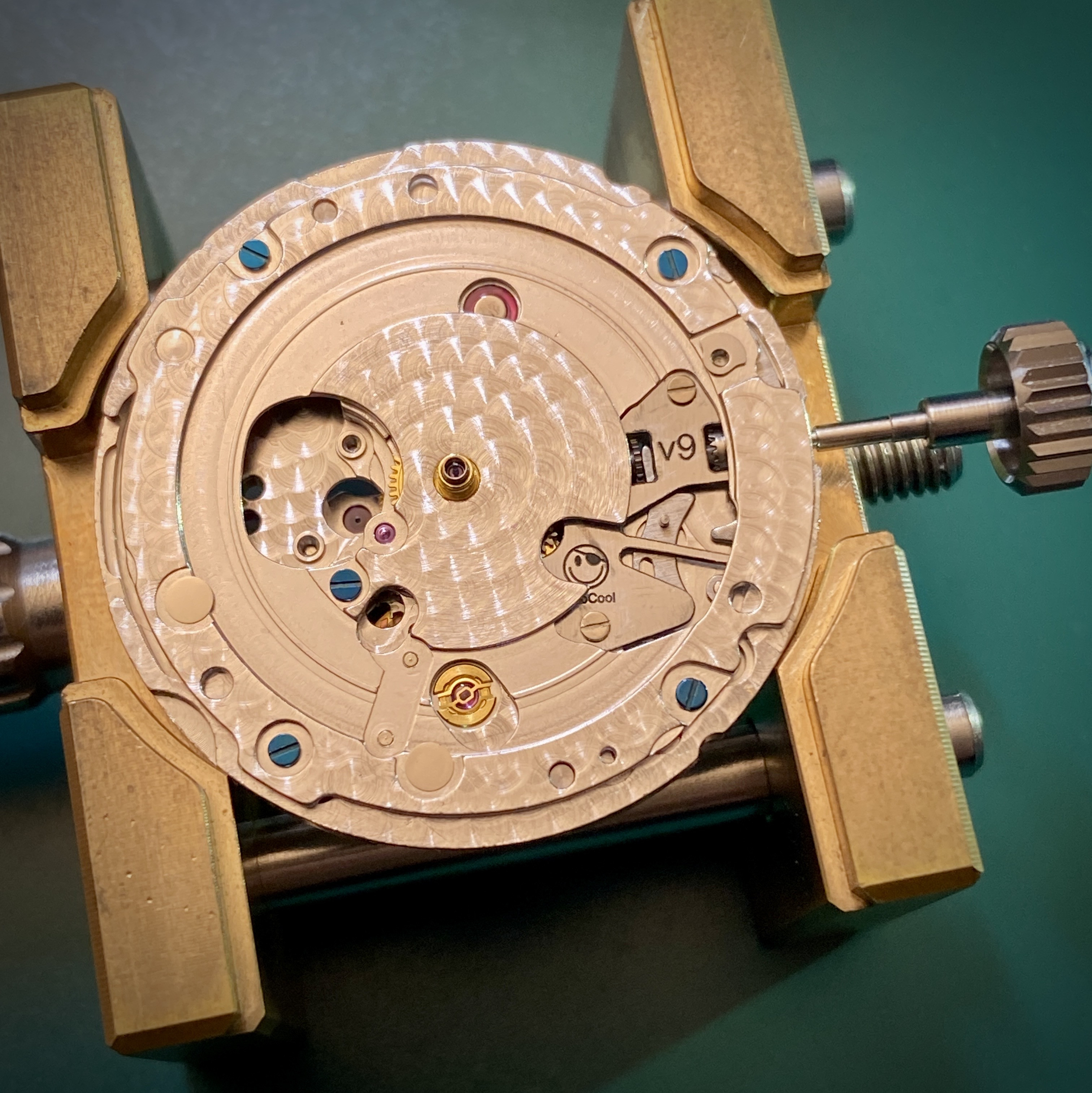
Here’s what the spring looks like in the fully assembled movement less the date works parts which are of no use.


I asked @xZeroCoolx if he positioned the logo so it would be visible through the old date corrector cutout in the date plate, but he said it was just a happy accident. Either way, I think it looks pretty crisp.


Here’s the final assembly… @CTbeforeLP sent me the watch without a dial or hands. (I didn’t case up the movement without a dial just to show off the custom part, although I do think it looks cool this way.)
 

dogwood

I'm Pretty Popular
Patron
Section Moderator
Certified
7/9/21
2,441
5,420
113
Canada
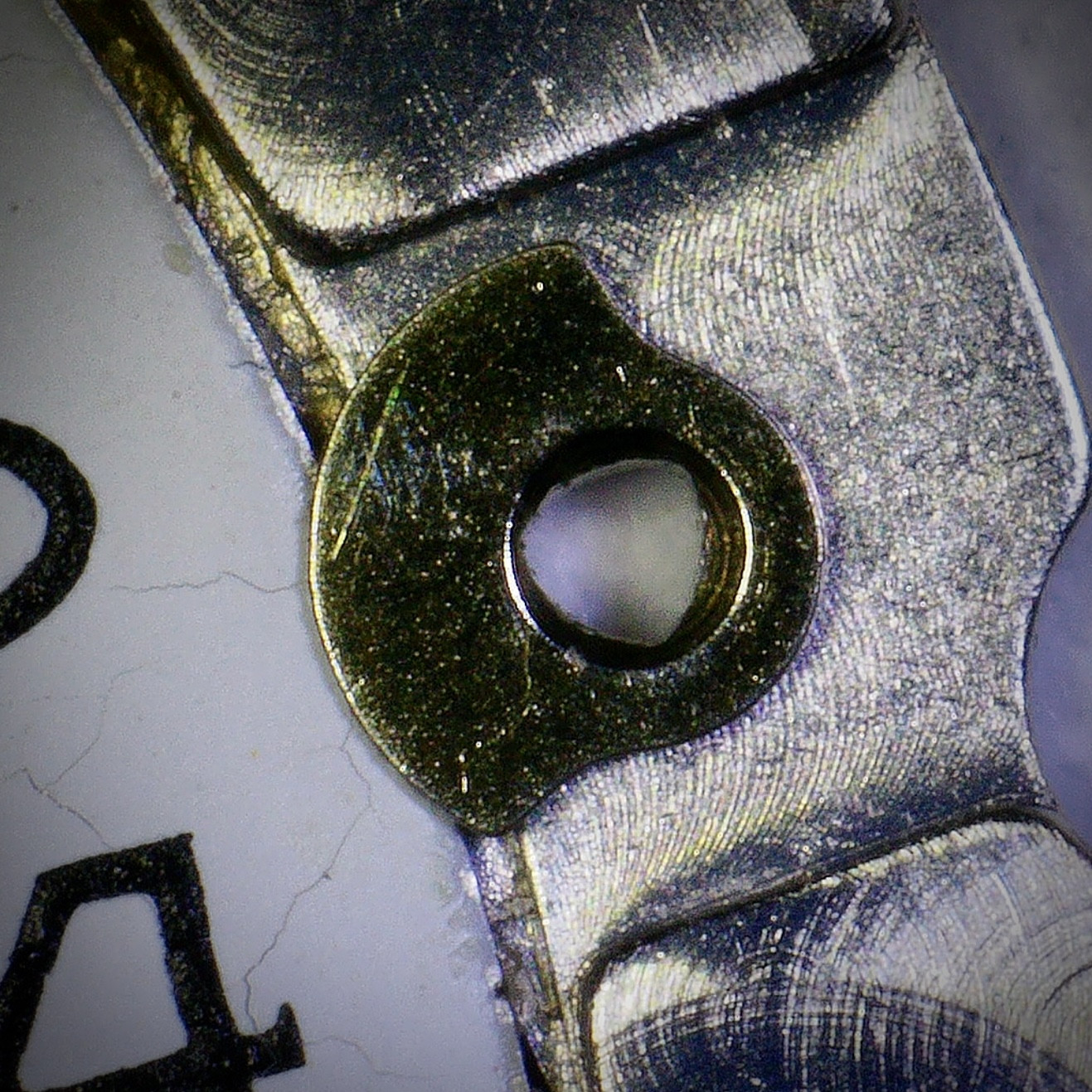
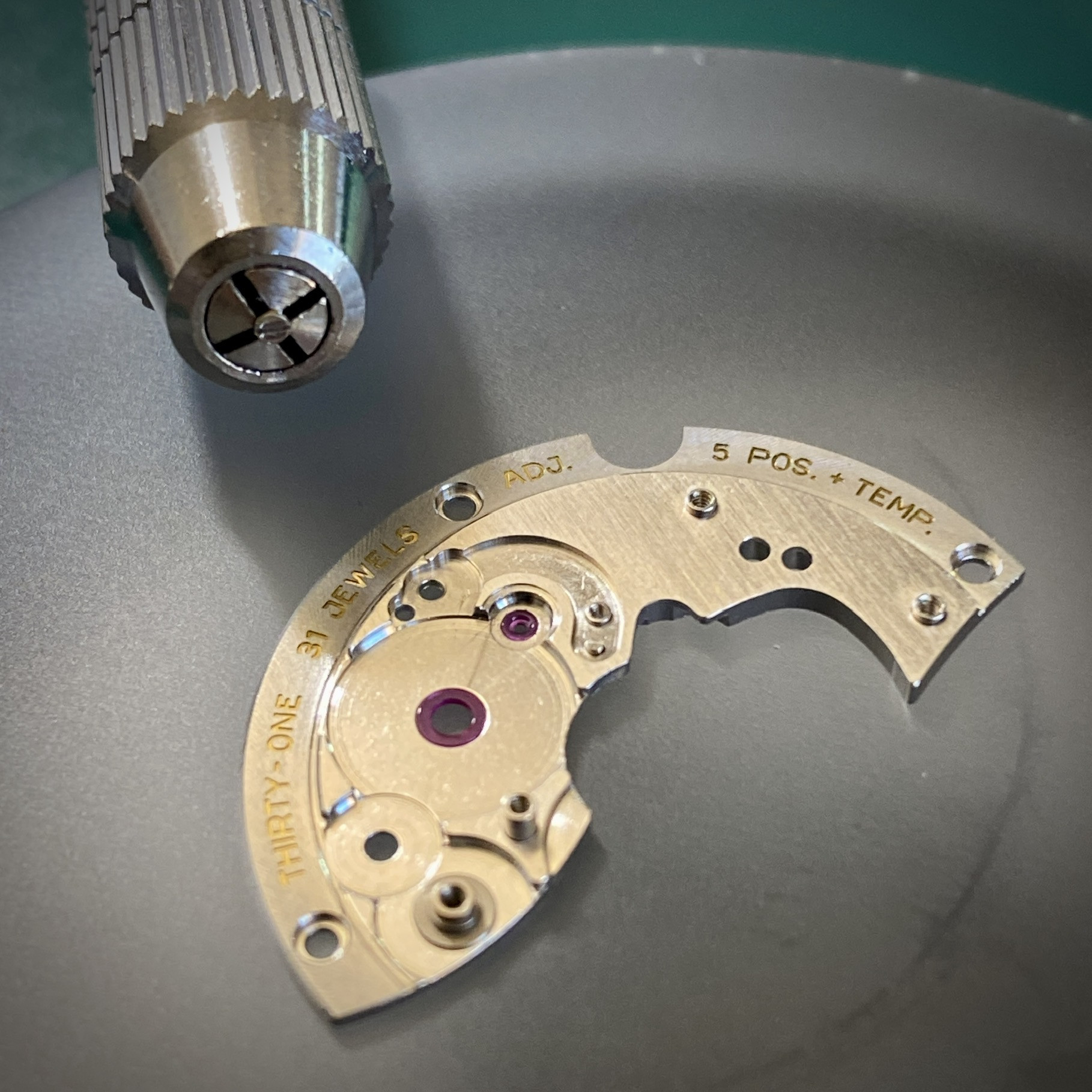
I was working on a VS3235 movement today when something interesting happened that’s never happened to me before: when I went to unscrew the click from the barrel bridge, the screw just kept spinning. But unlike the feeling when a screw head shears off, this time there was continuous resistance, but the screw never came out. After inspecting under the microscope I discovered that there was a threaded insert in the barrel bridge and it was the insert that was spinning, not the screw. My solution was to use my staking set to punch out the insert, and then use a pin vise to hold the insert to remove the screw.


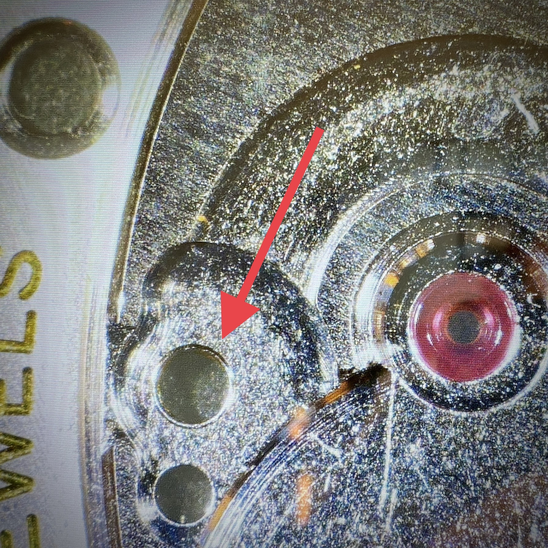
This worked, but it left me with the problem of how to secure the threaded insert back into the hole in the barrel bridge (red arrow). I’m new to the concept of staking parts together, but the basic idea seems simple enough: place the smaller part into the hole in the host part, then use a stake to upset the metal of the host to squeeze the small part in the hole.

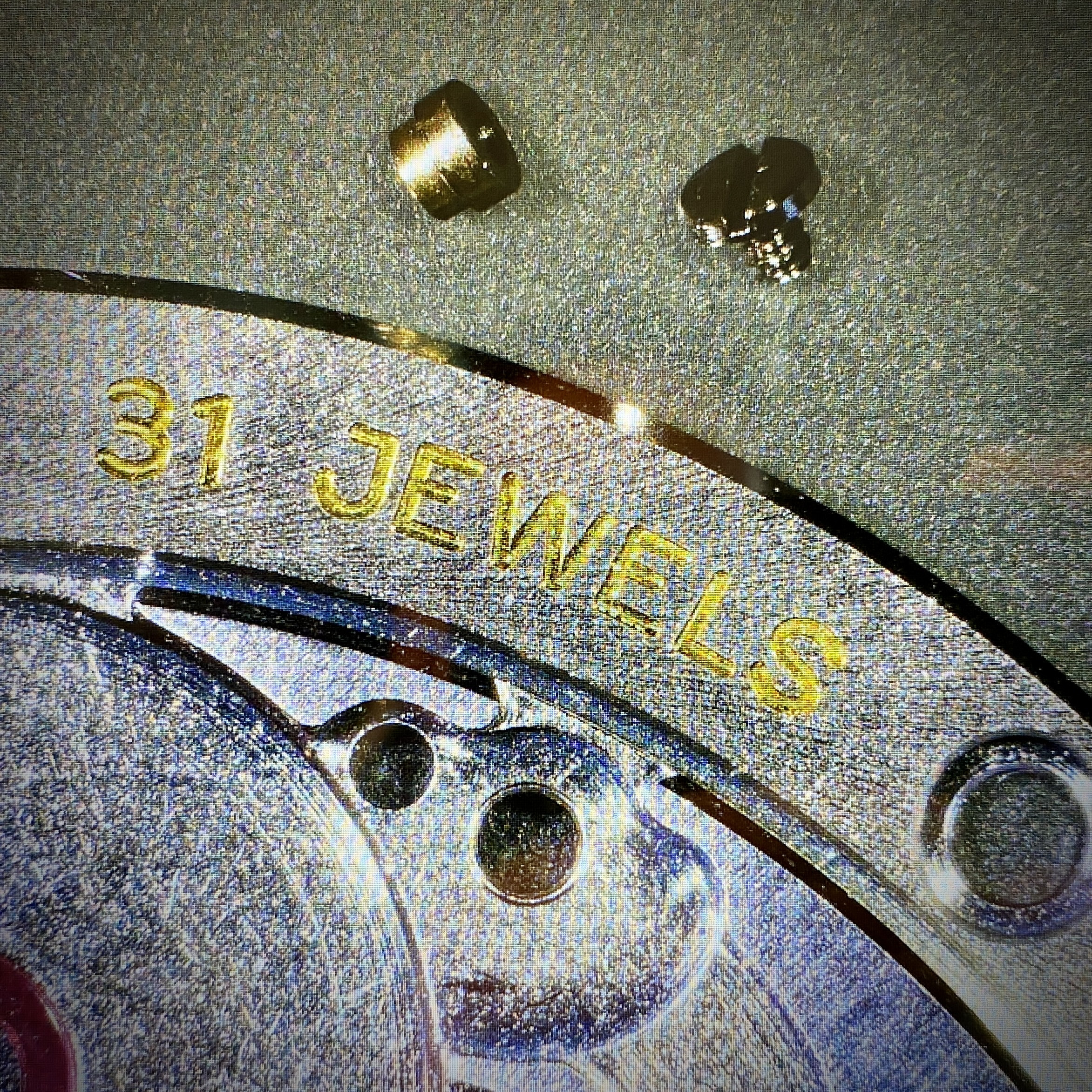
I’m not sure if I’m doing this correctly, I used a rounded tipped stake and made three punches as close as I could to the threaded insert. The stakes each left a little dimple in the barrel bridge where I tapped them in. Hopefully this has upset the metal enough to form a tight grip between the threaded insert and the barrel bridge. Before and after pics below:
 
  • Like
Reactions: Endo and Platomates

WatchSmith.US

-- Watchmaker --
Vendor (Watch Repair)
Certified
13/3/16
1,297
2,033
113
I was working on a VS3235 movement today when something interesting happened that’s never happened to me before: when I went to unscrew the click from the barrel bridge, the screw just kept spinning. But unlike the feeling when a screw head shears off, this time there was continuous resistance, but the screw never came out. After inspecting under the microscope I discovered that there was a threaded insert in the barrel bridge and it was the insert that was spinning, not the screw. My solution was to use my staking set to punch out the insert, and then use a pin vise to hold the insert to remove the screw.


This worked, but it left me with the problem of how to secure the threaded insert back into the hole in the barrel bridge (red arrow). I’m new to the concept of staking parts together, but the basic idea seems simple enough: place the smaller part into the hole in the host part, then use a stake to upset the metal of the host to squeeze the small part in the hole.

I’m not sure if I’m doing this correctly, I used a rounded tipped stake and made three punches as close as I could to the threaded insert. The stakes each left a little dimple in the barrel bridge where I tapped them in. Hopefully this has upset the metal enough to form a tight grip between the threaded insert and the barrel bridge. Before and after pics below:
Good save, Pete!!
 
  • Like
Reactions: dogwood

dogwood

I'm Pretty Popular
Patron
Section Moderator
Certified
7/9/21
2,441
5,420
113
Canada
A little more work on the 3230 setting lever spring project. I have a watch in on my bench for a service at the moment, and I'm going to be installing one of @xZeroCoolx's laser cut parts into it for testing. ZeroCool and I are still working out the final production process for this part (it should be widely available soon), but at the moment I'm still hand finishing the laser cut parts with sand paper up to 3000 grit. Then I'm cleaning the part in an ultrasonic cleaner to remove any residual grit from the hand finishing. But as a final step, ZeroCool suggested that we passivate the metal to ensure that there's the lowest possible chance of corrosion developing.

I've never passivated stainless steel before (although I have used benzotetratriazol as a passivator / corrosion inhibitor for the coolant in my custom PC cooling loop). But unlike passivating copper in a liquid cooling loop, passivating stainless steel is different. The stainless steel we're using (304 SS) is:
  • 17.5% to 19.5% Chromium
  • 8% to 10.5% Nickel
  • 2% Manganese
  • 1% Silicon
  • Trace amounts (<0.1%) of Nitrogen, Carbon, Phosphorus, and Sulfur
  • Balance of Iron
The way that stainless steel is passivated is to immerse the part in either Nitric or Citric acid to dissolve away any free iron on the surface of the part, leaving the surface of the part as Chromium and Nickel which both quickly form a protective oxide patina.

My DIY method was to first degrease the part using 99.9% IPA as a first bath, then after drying the part, using a second bath of Acetone to remove any oils that might have made it onto the part from my fingers during the hand finishing. Then I prepared a concentrated solution of citric acid at 50C and left the part in the solution for 20 minutes. Below is a time lapse of the part in the bath. It's not terribly exciting, but you can see that initially there were a lot of bubbles as the surface iron was eaten away by the acid, but then the bubble formation rate decreased and eventually slowed to a stop. Hopefully this means that all the of surface iron has been removed.


Here's the finished part, and for comparison the stock Dandong part at the same magnification.
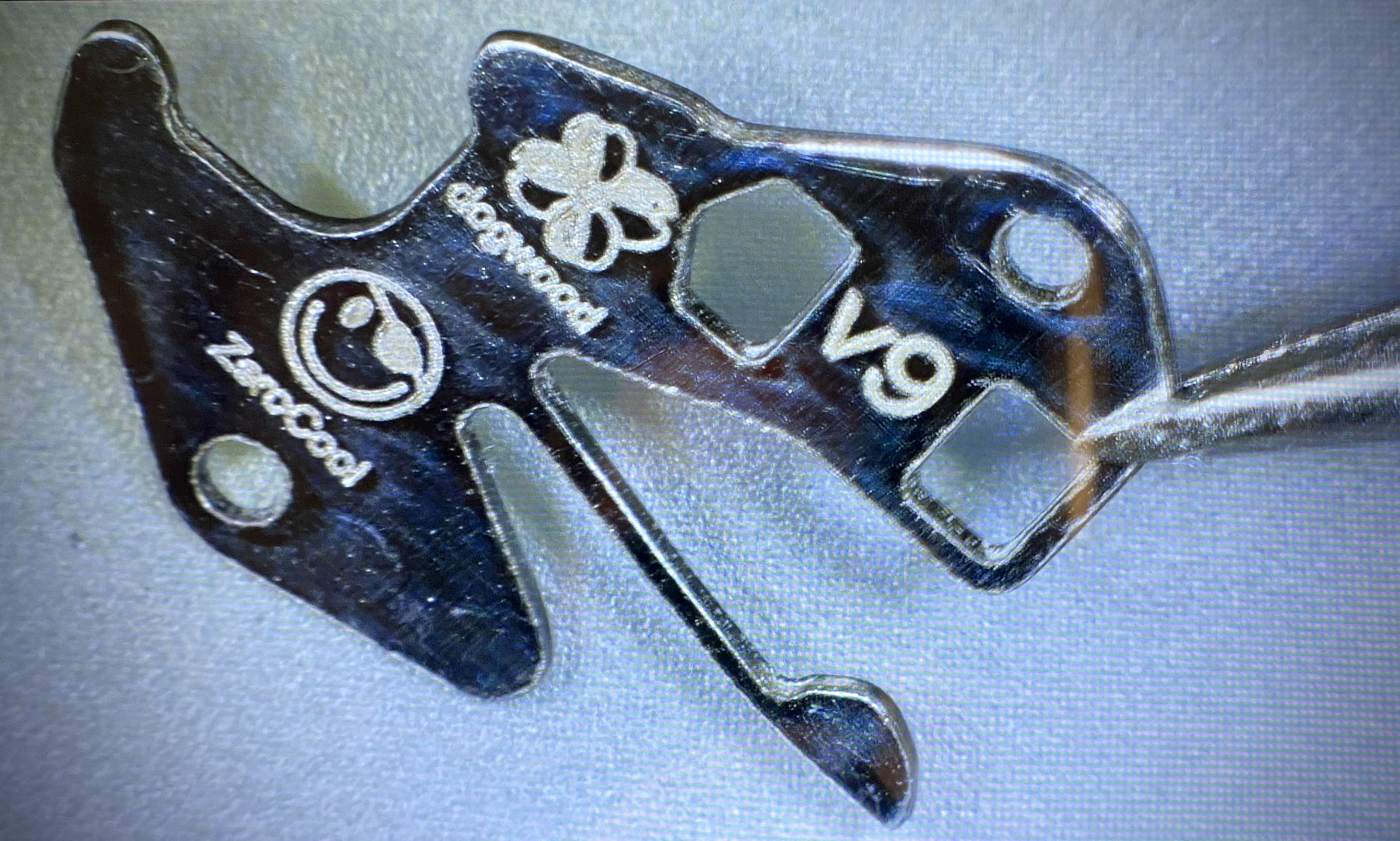


In order to get these parts widely available, we need to develop a way of finishing the edge profile of the part to be as smooth as possible without having to hand finish the each individual part. ZeroCool has been doing a LOT of testing on this, and we might have a method involving a rock tumbler and a combination of grits that effectively deburrs and smooths the edge profile. It's not a fast process, but it might be a "hands free" process, which is what we're looking for. The pic below is from ZeroCool and shows the casualties of production testing...


We've also looked into stamping the parts since they're thin sheet metal parts... I even ran the calculations for 0.25mm 304 stainless, and for our part geometry the force required for stamping would only about about 750kg, which would be easy enough to generate on a manual arbor press. But stamping requires precision tools and dies to be made. I contacted a few tool and die makers, but the cost would be high, and I was warned that 1) the tool may not last that long because the long skinny spring arm is quite thin, so the tool that punches it out may break after very few actuations; and 2) stamped parts don't have very good edge finishes since the sheet metal both shears, but also tears. The way to solve the tearing problem with stamping is to do an operation called "Fine Blanking" which is where the tool and die are far more complex and the metal parts getting punched are supported by a counter punch as they are sheared. The problem with "fine blanking" is that the tooling costs at least $50K... so that's kind of out of the question. One final option, is production wire electronic discharge machining. Wire EDM is a process where a thin copper wire is threaded through metal and a high voltage is put on the wire, as the wire approaches the stock material a spark jumps across and erodes away the stock material (and the wire, but the wire is cycled through from a large spool, so there's always fresh wire). Wire EDM is the process that produces those amazing metal parts that slide together and have no seam. But Wire EDM is also expensive and offers levels of precision that just aren't required for this part. But is doesn't have the HUGE upfront costs of tooling that fine blanking does.

Anyway... TLDR: the VS3230 setting lever spring project is progressing and hopefully soon these parts will be available to the community.
 

Platomates

Getting To Know The Place
5/6/23
83
27
18
Singapore
A little more work on the 3230 setting lever spring project. I have a watch in on my bench for a service at the moment, and I'm going to be installing one of @xZeroCoolx's laser cut parts into it for testing. ZeroCool and I are still working out the final production process for this part (it should be widely available soon), but at the moment I'm still hand finishing the laser cut parts with sand paper up to 3000 grit. Then I'm cleaning the part in an ultrasonic cleaner to remove any residual grit from the hand finishing. But as a final step, ZeroCool suggested that we passivate the metal to ensure that there's the lowest possible chance of corrosion developing.

I've never passivated stainless steel before (although I have used benzotetratriazol as a passivator / corrosion inhibitor for the coolant in my custom PC cooling loop). But unlike passivating copper in a liquid cooling loop, passivating stainless steel is different. The stainless steel we're using (304 SS) is:
  • 17.5% to 19.5% Chromium
  • 8% to 10.5% Nickel
  • 2% Manganese
  • 1% Silicon
  • Trace amounts (<0.1%) of Nitrogen, Carbon, Phosphorus, and Sulfur
  • Balance of Iron
The way that stainless steel is passivated is to immerse the part in either Nitric or Citric acid to dissolve away any free iron on the surface of the part, leaving the surface of the part as Chromium and Nickel which both quickly form a protective oxide patina.

My DIY method was to first degrease the part using 99.9% IPA as a first bath, then after drying the part, using a second bath of Acetone to remove any oils that might have made it onto the part from my fingers during the hand finishing. Then I prepared a concentrated solution of citric acid at 50C and left the part in the solution for 20 minutes. Below is a time lapse of the part in the bath. It's not terribly exciting, but you can see that initially there were a lot of bubbles as the surface iron was eaten away by the acid, but then the bubble formation rate decreased and eventually slowed to a stop. Hopefully this means that all the of surface iron has been removed.


Here's the finished part, and for comparison the stock Dandong part at the same magnification.
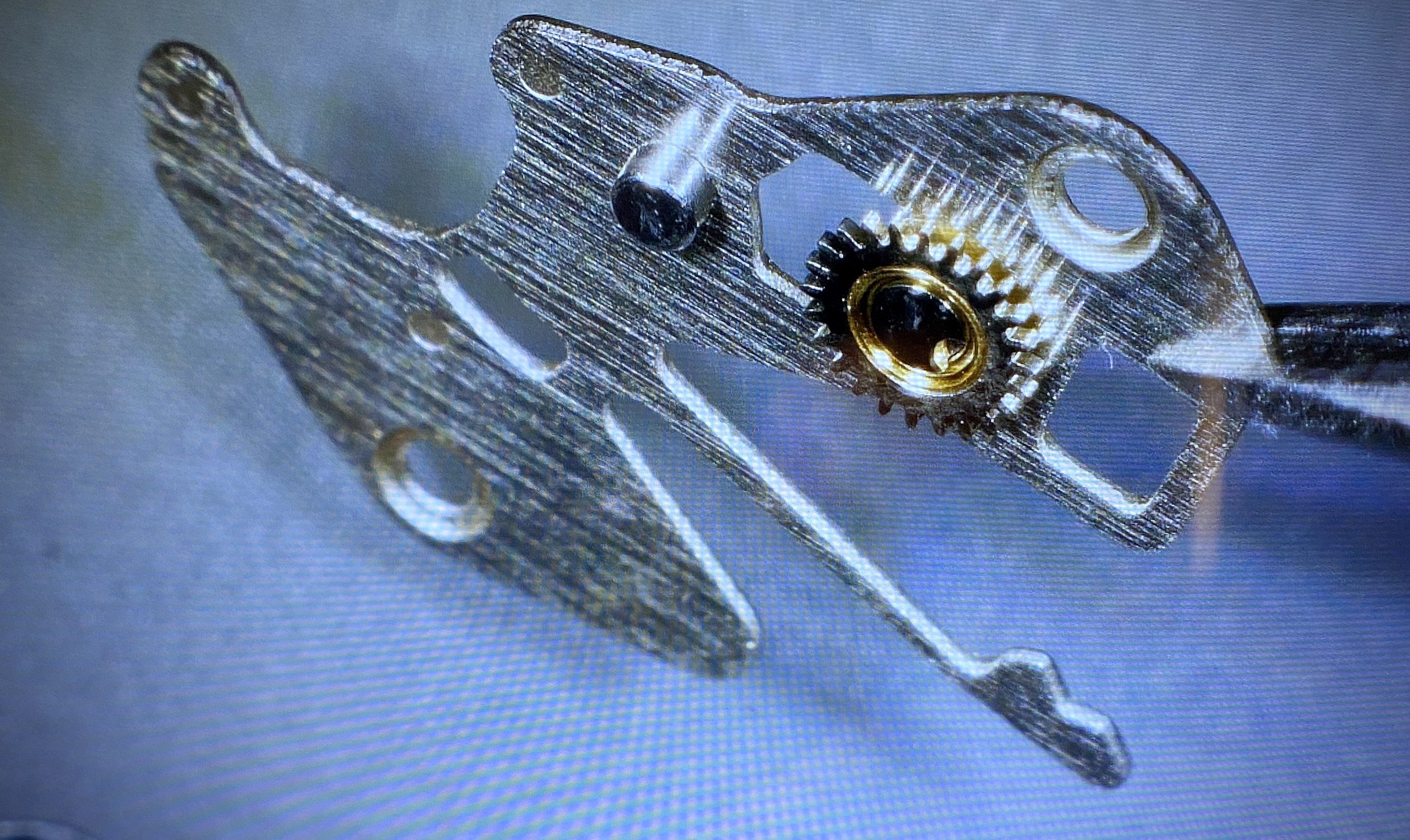


In order to get these parts widely available, we need to develop a way of finishing the edge profile of the part to be as smooth as possible without having to hand finish the each individual part. ZeroCool has been doing a LOT of testing on this, and we might have a method involving a rock tumbler and a combination of grits that effectively deburrs and smooths the edge profile. It's not a fast process, but it might be a "hands free" process, which is what we're looking for. The pic below is from ZeroCool and shows the casualties of production testing...
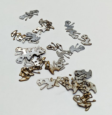


We've also looked into stamping the parts since they're thin sheet metal parts... I even ran the calculations for 0.25mm 304 stainless, and for our part geometry the force required for stamping would only about about 750kg, which would be easy enough to generate on a manual arbor press. But stamping requires precision tools and dies to be made. I contacted a few tool and die makers, but the cost would be high, and I was warned that 1) the tool may not last that long because the long skinny spring arm is quite thin, so the tool that punches it out may break after very few actuations; and 2) stamped parts don't have very good edge finishes since the sheet metal both shears, but also tears. The way to solve the tearing problem with stamping is to do an operation called "Fine Blanking" which is where the tool and die are far more complex and the metal parts getting punched are supported by a counter punch as they are sheared. The problem with "fine blanking" is that the tooling costs at least $50K... so that's kind of out of the question. One final option, is production wire electronic discharge machining. Wire EDM is a process where a thin copper wire is threaded through metal and a high voltage is put on the wire, as the wire approaches the stock material a spark jumps across and erodes away the stock material (and the wire, but the wire is cycled through from a large spool, so there's always fresh wire). Wire EDM is the process that produces those amazing metal parts that slide together and have no seam. But Wire EDM is also expensive and offers levels of precision that just aren't required for this part. But is doesn't have the HUGE upfront costs of tooling that fine blanking does.

Anyway... TLDR: the VS3230 setting lever spring project is progressing and hopefully soon these parts will be available to the community.
I love you man.
 
  • Like
Reactions: dogwood

OnTheSly

Getting To Know The Place
24/6/23
51
47
18
Best Coast
An interesting issue came up this morning when I was working on a VSF 8500 Omega movement.
Nice job with a creative fix.


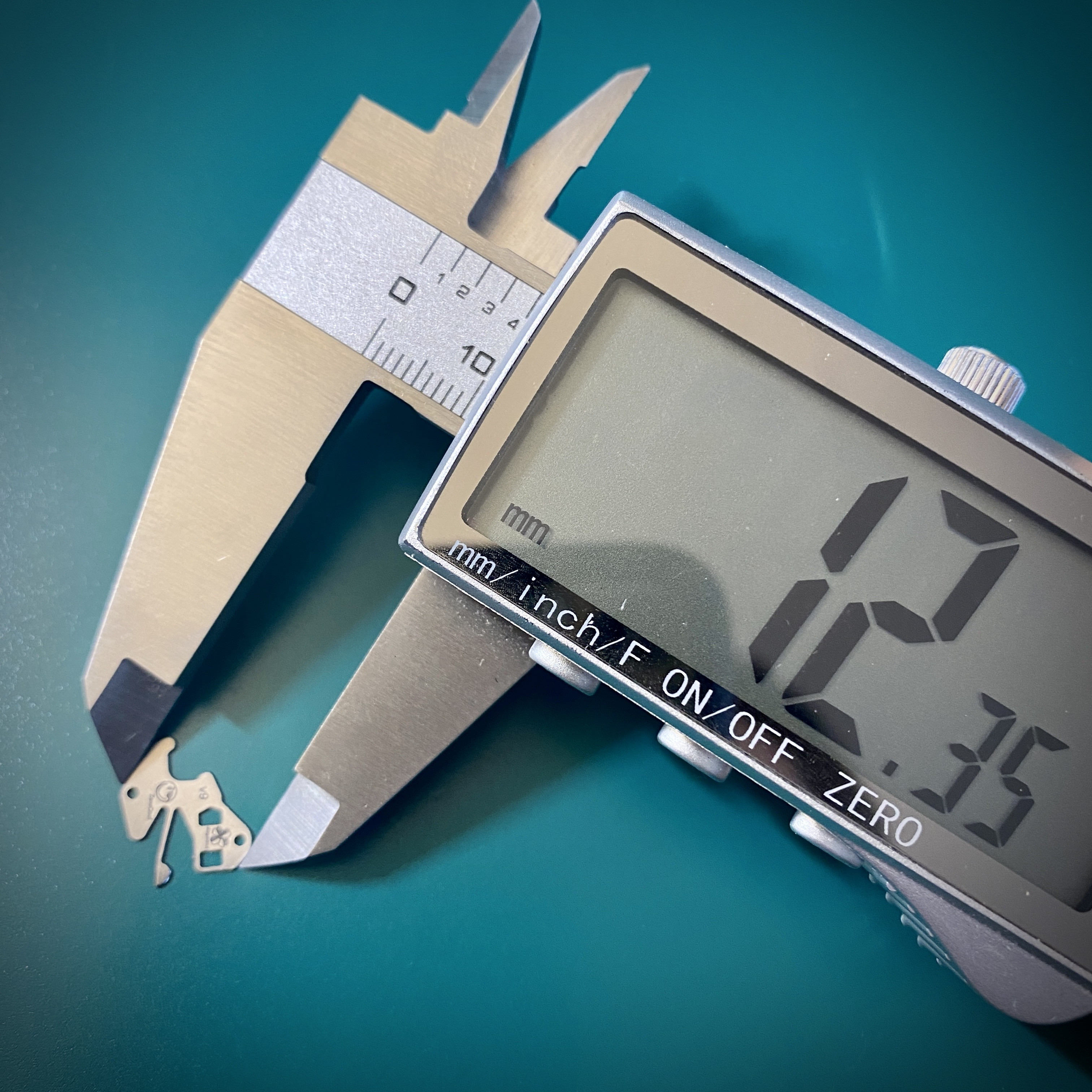
Do you recall what mainspring winder you used for the 8500? I am working on a VSF 8900 movement and the masinspring inner coil measures about 2mm and none of the arbors from my Bergeon winders come close to fitting that so I thought that one of the 8500-1 or 8500-2 winders I got from Aliexpress would work as their arbors are close to that. The 8500-1 arbor is 1.9mm and the hook doesn't catch the hole as the inner coil is a tad too big. The 8500-2 arbor is a bit too large such that when trying to remove the mainspring after winding it into the drum it is on the arbor so tightly that it just doesn't want to come out. I tried for a good 15 minutes and even with the hook disengaged it won't come off it is on there so tightly. My next step is to anneal and then reshape the inner coils smaller and use the 8500-1 arbor but I was hoping you had better sucess when you serviced the 8500. Any tips you have would be appreciated!
 

dogwood

I'm Pretty Popular
Patron
Section Moderator
Certified
7/9/21
2,441
5,420
113
Canada
Nice job with a creative fix.


Do you recall what mainspring winder you used for the 8500? I am working on a VSF 8900 movement and the masinspring inner coil measures about 2mm and none of the arbors from my Bergeon winders come close to fitting that so I thought that one of the 8500-1 or 8500-2 winders I got from Aliexpress would work as their arbors are close to that. The 8500-1 arbor is 1.9mm and the hook doesn't catch the hole as the inner coil is a tad too big. The 8500-2 arbor is a bit too large such that when trying to remove the mainspring after winding it into the drum it is on the arbor so tightly that it just doesn't want to come out. I tried for a good 15 minutes and even with the hook disengaged it won't come off it is on there so tightly. My next step is to anneal and then reshape the inner coils smaller and use the 8500-1 arbor but I was hoping you had better sucess when you serviced the 8500. Any tips you have would be appreciated!
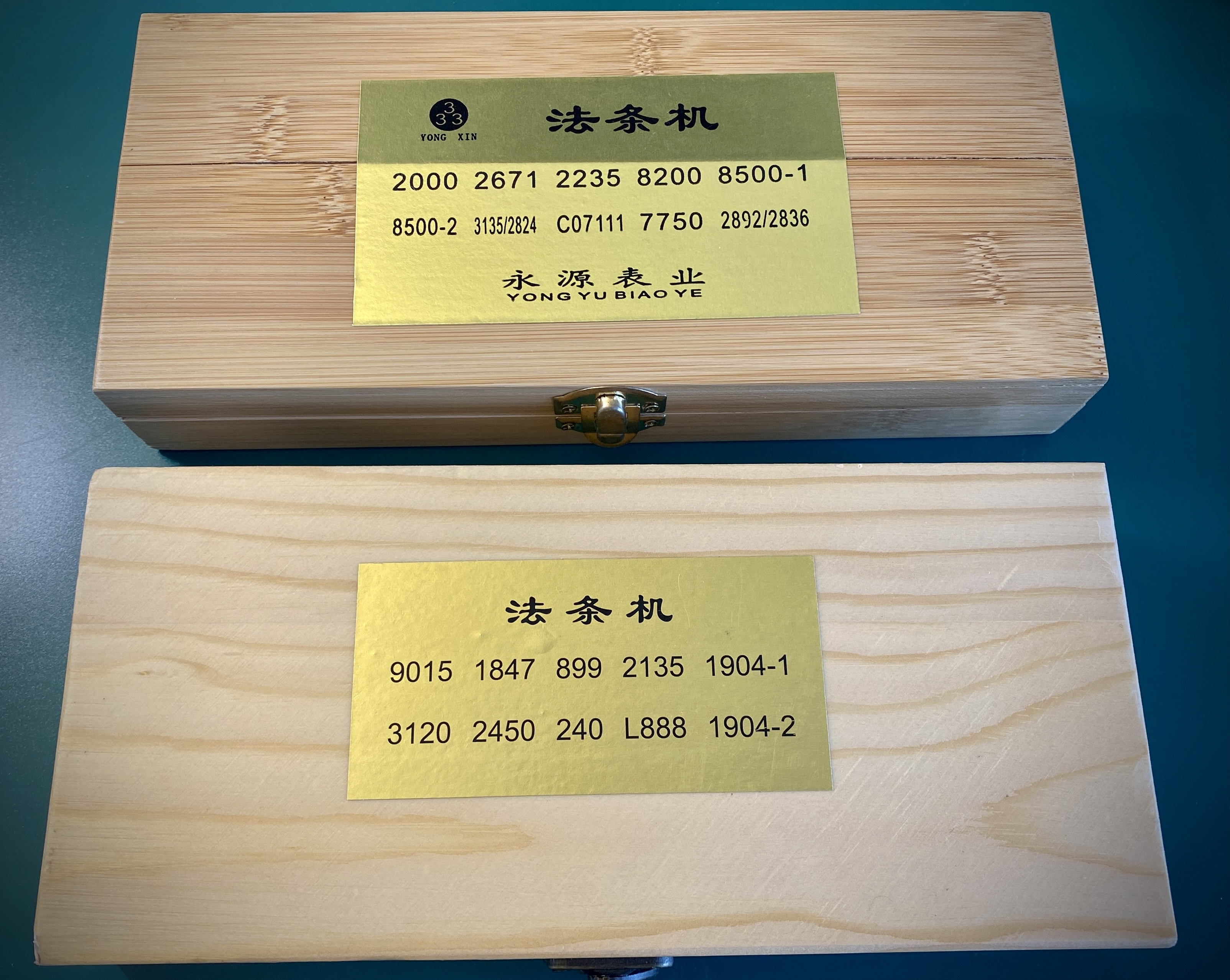
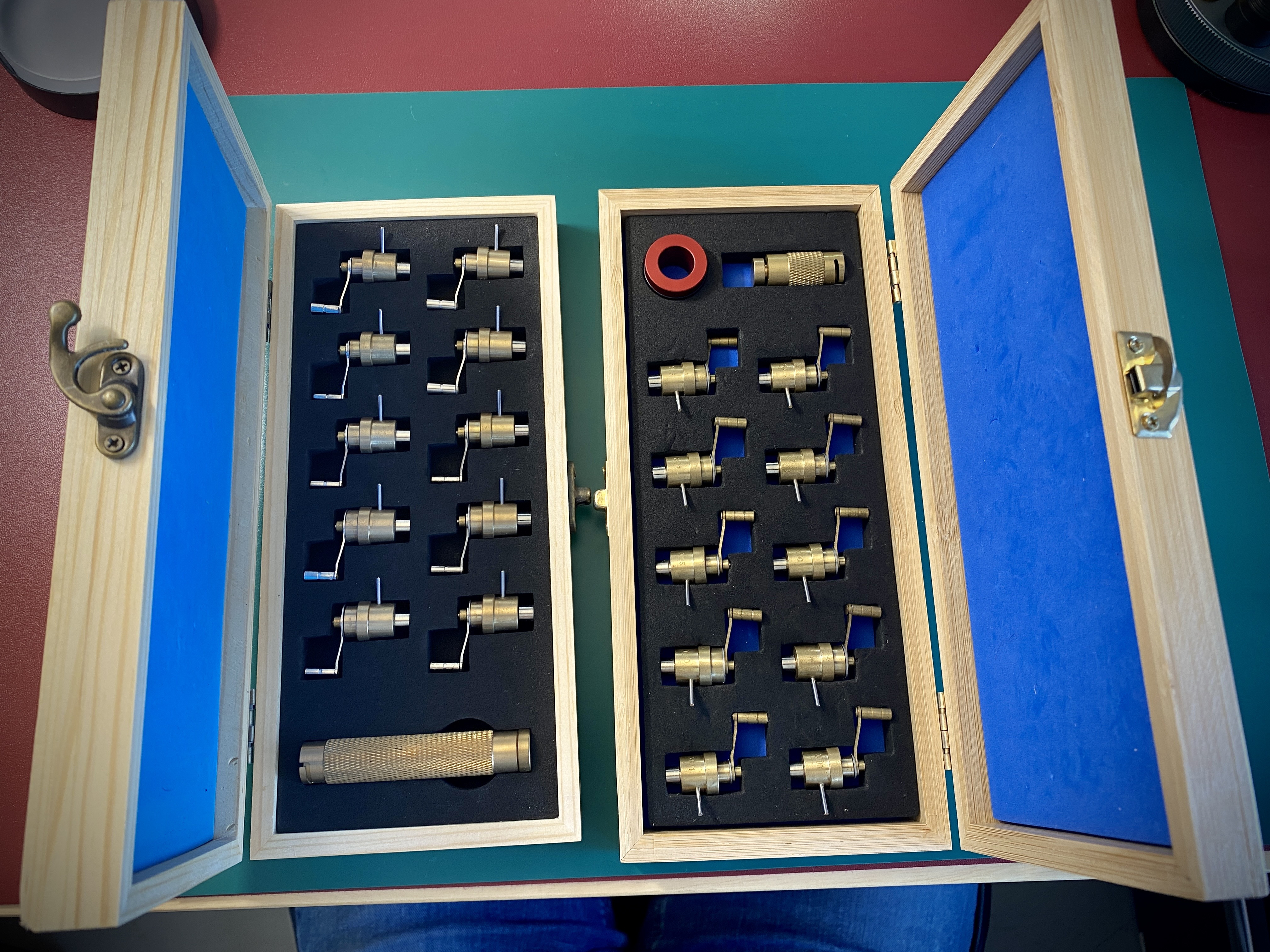
I don’t remember which winder I used. I have two boxes of winders from AliExpress. I think these are the two most common ones you’ll find…


I suspect I used the 8500-1 winder, and maybe just got lucky enough to get the arbor to hook.
 
  • Like
Reactions: OnTheSly

OnTheSly

Getting To Know The Place
24/6/23
51
47
18
Best Coast
Thanks for checking. The ones I have look just like yours, same box too. Might be a tolerance issue where my arbor is just slightly off.
 

dogwood

I'm Pretty Popular
Patron
Section Moderator
Certified
7/9/21
2,441
5,420
113
Canada
A quick update on the 3230 setting lever spring that @xZeroCoolx and I are working on. ZeroCool sent me our first batch of production test parts. There are two bits of good news, and one bit of bad news.

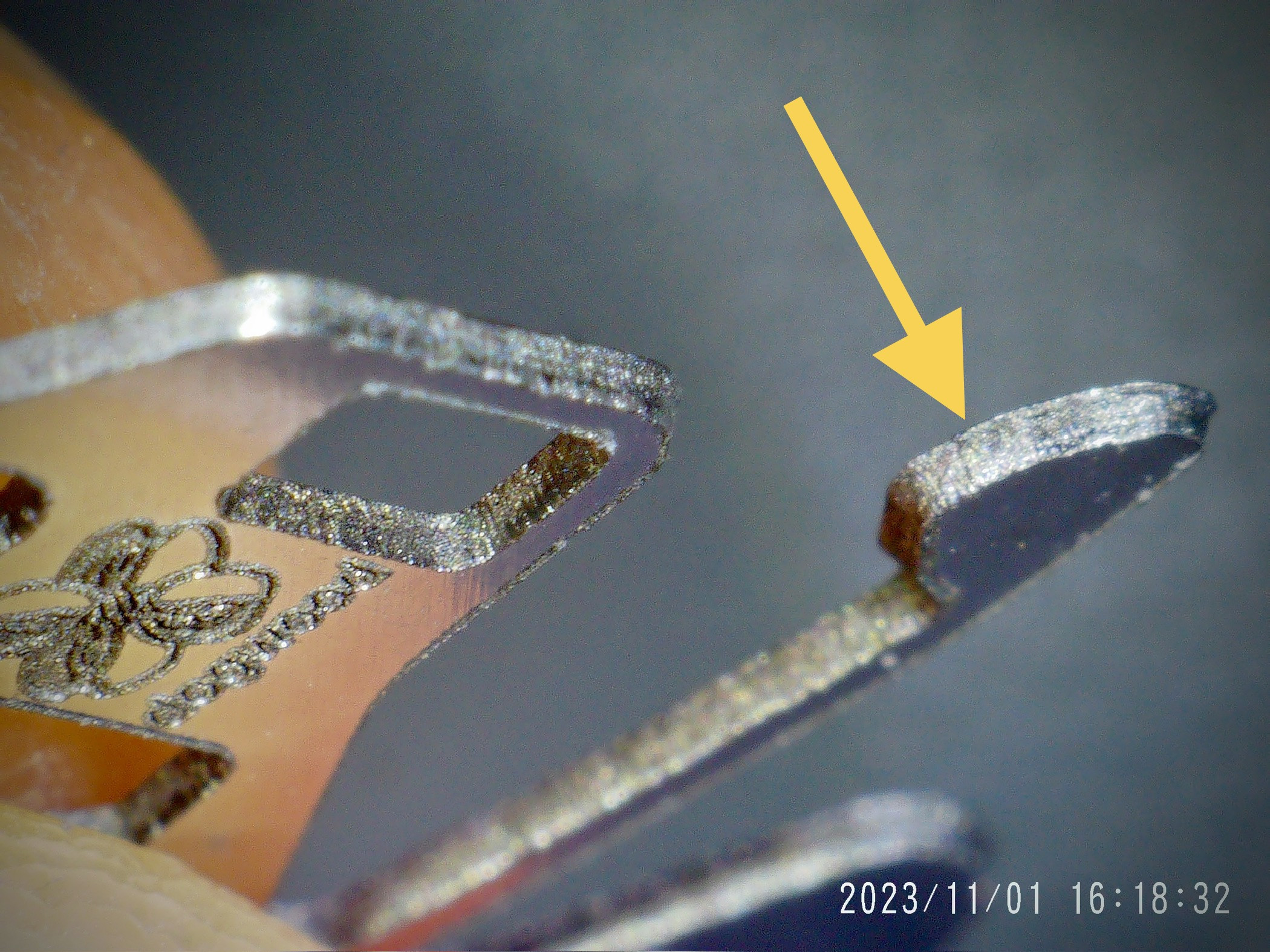
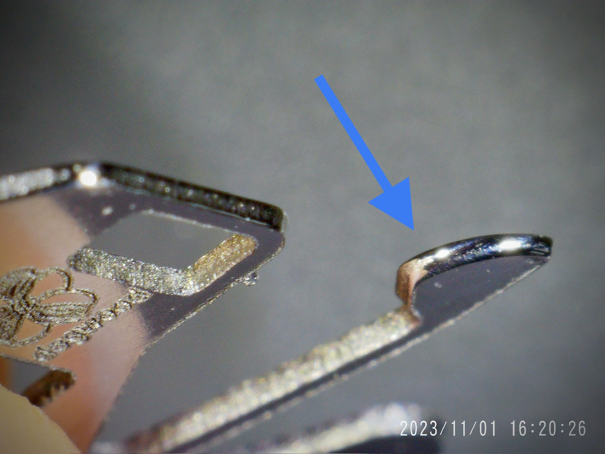
Good news first… ZeroCool has figured out a deburring and lobe polishing proceedure that’s relatively hands off; and for the steps that are hands on relatively efficient. Here are some pics of the deburred part (yellow arrow), and the part after lobe polishing (blue arrow). I think the level of polish we’re getting is actually better than the stock Dandong 3235 part (see pics in the post a few above)


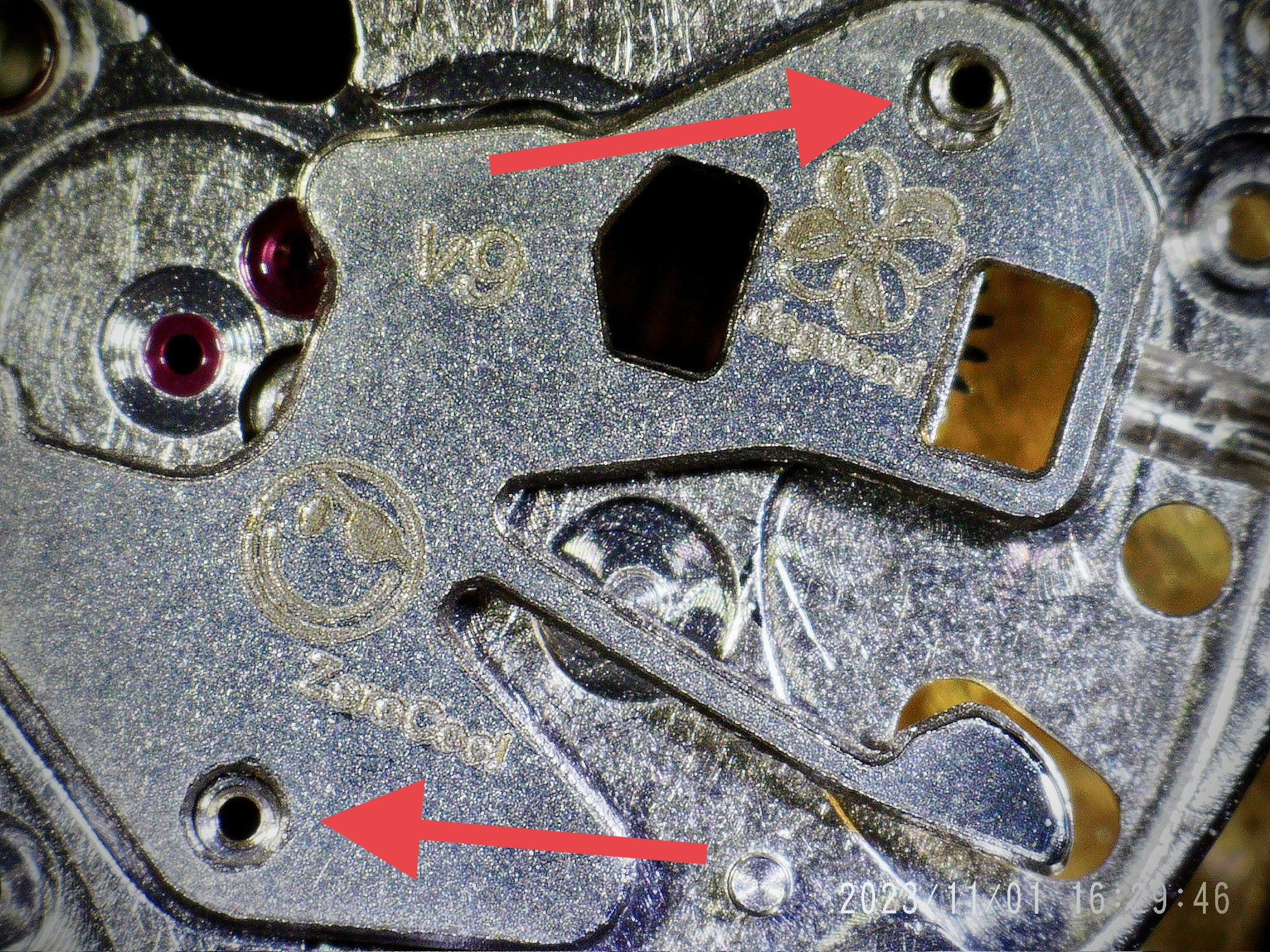
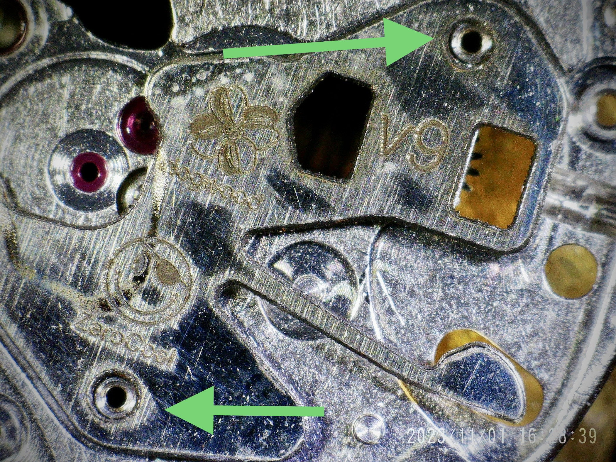
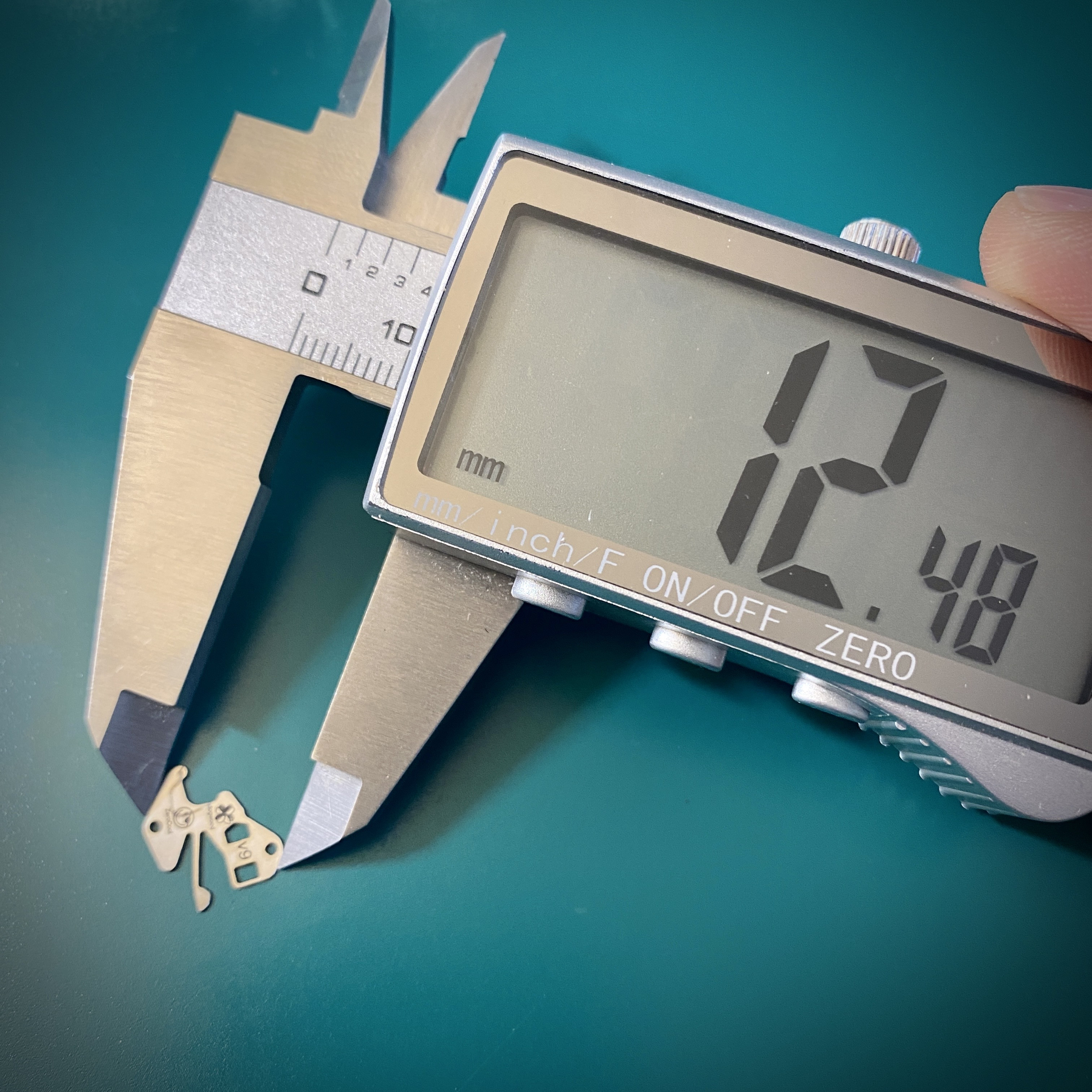
ZeroCool has also upgraded to a more efficient fiber laser cutting lens — a 150mm lens. Previously he was using a 75mm lens. The 150mm lens gives 4x the engraving area, so it allows for a single setup to cut 4x the number of parts. However, we hit an unanticipated problem. As the laser no longer comes down from the source as vertically, the geometry of the parts gets distorted. Unfortunately the dimensional tolerances of this part are quite tight, so even a 1% projection distortion means the cut part no longer fits properly onto the mounting posts on the main plate. The difference between a part cut on the 75mm lens (green arrows) vs 150mm lens (red arrows) is small, but enough that the parts don’t fit.


Measuring the parts from the previous test run on the 75mm vs the new run with the 150mm lens shows a difference of about 1%.


There’s truth to the saying “hardware is hard”… I was a software guy in my previous life, and i’m getting a whole new level of respect for engineers who do hardware.

I’m going to be sending ZeroCool and spare VS3235 mainplate to use as a testing jig to see if we can fix the 150mm projection scale issue. If it’s fixable that’ll be a big win for production efficiency.
 

Platomates

Getting To Know The Place
5/6/23
83
27
18
Singapore
A quick update on the 3230 setting lever spring that @xZeroCoolx and I are working on. ZeroCool sent me our first batch of production test parts. There are two bits of good news, and one bit of bad news.

Good news first… ZeroCool has figured out a deburring and lobe polishing proceedure that’s relatively hands off; and for the steps that are hands on relatively efficient. Here are some pics of the deburred part (yellow arrow), and the part after lobe polishing (blue arrow). I think the level of polish we’re getting is actually better than the stock Dandong 3235 part (see pics in the post a few above)


ZeroCool has also upgraded to a more efficient fiber laser cutting lens — a 150mm lens. Previously he was using a 75mm lens. The 150mm lens gives 4x the engraving area, so it allows for a single setup to cut 4x the number of parts. However, we hit an unanticipated problem. As the laser no longer comes down from the source as vertically, the geometry of the parts gets distorted. Unfortunately the dimensional tolerances of this part are quite tight, so even a 1% projection distortion means the cut part no longer fits properly onto the mounting posts on the main plate. The difference between a part cut on the 75mm lens (green arrows) vs 150mm lens (red arrows) is small, but enough that the parts don’t fit.


Measuring the parts from the previous test run on the 75mm vs the new run with the 150mm lens shows a difference of about 1%.


There’s truth to the saying “hardware is hard”… I was a software guy in my previous life, and i’m getting a whole new level of respect for engineers who do hardware.

I’m going to be sending ZeroCool and spare VS3235 mainplate to use as a testing jig to see if we can fix the 150mm projection scale issue. If it’s fixable that’ll be a big win for production efficiency.
hey boss, once its ready to released in the market, I will purchase a VSF 124060 and your 3230 setting lever 😇
 
  • Like
Reactions: dogwood