• Tired of adverts on RWI? - Subscribe by clicking HERE and PMing Trailboss for instructions and they will magically go away!

Servicing a ZF AP 15400 Clone 3120 Movement

dogwood

I'm Pretty Popular
Patron
Certified
7/9/21
1,901
3,580
113
Canada
I noticed that me ZA AP 15400 was running a bit fast (about +45s/d) so I decided I would take a look at regulating it. But when I started looking at the regulation mechanism through my digital microscope to figure out where the beat adjustor and regulator arms actually are (they aren't as obviously positioned as these things are on a VR3235, VS3235, or N4130 movement), I noticed that the movement was filthy. At first I thought it might have been dust / grit on the transparent caseback, but after adjusting the focus on the microscope, it's very clear that there's dust (and event hair / lint) everywhere inside the movement.

zq0Ybk.jpg

zq0OXD.jpg

zq0IqY.jpg

zq01Uo.jpg

zq09BJ.jpg

zq0nRP.jpg


And this brought me to the idea of servicing the clone 3120 movement that's inside my ZF AP 15400. I searched and couldn't find a post where anybody had documented a teardown or service of this movement... but I'm hoping that somebody has and can perhaps give me some guidance. Also (and I know this is a long shot), does anybody have a service manual for this movement (or a movement in the same family)? I'm guessing the movement is pretty standard since it doesn't have any real complications other than a center seconds and date (without a quick date change function).
 

dogwood

I'm Pretty Popular
Patron
Certified
7/9/21
1,901
3,580
113
Canada
Ok, here we go… here is the baseline performance of the movement *before* I’ve done anything to it.

zIjahp.jpg


At the very least, it needs to be regulated. But that ripple / wave in the time grapher is telling me that there’s something funky going on with the escape wheel — as in, as the escape wheel turns through 360 degrees, on one side it runs fast and on the other it runs slower.
 

dogwood

I'm Pretty Popular
Patron
Certified
7/9/21
1,901
3,580
113
Canada
Progress update:

I started by opening up the case from the back. The screws all came free pretty easily, except one of the bezel side hex head "nuts" didn't actually come free of the bezel. I didn't force it and will simply re-attach it in place once I re-assemble the watch.

With the bezel and caseback free, I opted to remove the hands since there was no crystal on the front of the watch anymore, and I'd have to flip the watch over to remove the stem. Removing the hands was easy thanks to a new set of hand removal levers that have arrived in the mail. I used a double layer of saran wrap as a dial protector and wooden tweezers to make sure I didn't mar up the hands when I moved them to my parts tray.

Next it was removing the stem and getting the movement out of the case. Unlike rolex movements, the stem is released not by pressing down a little pusher, but rather by unscrewing a set screw. This was easy enough and the stem came free, and I was able to remove the movement and dial from the watch case.

Then came the problem of either removing the dial or removing the rotor. I figured I'd try to remove the rotor first since it would make it easier to hold the movement as I manipulated it to get the dial off. Initially I unscrewed the two tiny screws at the hub of the rotor, but this didn't seem to free the rotor. I then screwed these screws back in, and instead decided to remove what I thought was the "automatic model". It turns out, the bridge that the rotor is connected to is actually the main train bridge. At this point I still hadn't unwound the main spring, so I was a bit terrified when the rotor + bridge came free and I saw un-supported train wheels underneath. This was clearly a mistake, and as I was trying to get the stem back into the movement to apply a bit of winding pressure and hold the click back to slowly release the main spring's energy, the train wheels jumped out of the movement on me. I picked them up, and inspected them, and none of them look damaged, but lesson learned... this is NOT the correct way to disassemble a ZF clone 3120 movement.

My next problem is trying to get the dial off. It looks like there are two set screws to secure dial feet... unlike on rolex movements where these set screws are radial (as in point towards the center of the movement), the two set screws I found are tangential (they point along the edge of the circle of the movement and are positioned in small recesses). I loosened these set screws, but then realized that they weren't actually clamping anything. It looks like the ZF dial doesn't have dial feet. But for some reason it still won't come free. I'm loath to apply to my prying force, but after playing with it for around 20 minutes, I can't figure out how it's secured in place. Tagging @legend since hopefully he's worked on a clone 3120 movement before and can offer a suggestions on how to remove the dial.

And finally I removed the balance bridge to get it out of the way since I was doing a lot of holding the movement as I looked for the way to remove the dial, I didn't want to damage this sensitive part. The balance looks really hard to regulate with the regulation arm positioned directly under the balance bridge. I guess this isn't a problem on the gen movement since it uses a balance wheel that has adjustable weights, but it's going to make it a huge hassle to regulate the clone.

And finally some pictures:

zIjJjF.jpg

zIjVOt.jpg

zIjbv5.jpg

zIjck2.jpg

zIjgJE.jpg

zIzZan.jpg

zIzzFs.jpg

zIzjp3.jpg

zIzHAY.jpg

zIzK8D.jpg

zIzhvk.jpg

zIzAzo.jpg

zIzLOJ.jpg

zIzekP.jpg

zIj06p.jpg
 

dogwood

I'm Pretty Popular
Patron
Certified
7/9/21
1,901
3,580
113
Canada
Update...

I still haven't been able to figure out a way to remove the dial, but since the dial is pretty safe resting against the movement cushion, I opted to "just keep digging" down through the movement to see if an obvious way of separating the dial came to light. Spoiler Warning: It did not.

First I removed the center wheel bridge and the center wheel. This was pretty easy although I have to say it was odd that it was secured using two different sized screws. But then my bias is rolex movements where the screw size differences are really subtle.

Next was removing the automatic module / section bridge. This was also pretty straight forward. Two screws secured the bridge and once it came free all the pinions and wheels within the automatic module came up smoothly. I'm not sure if that double wheel thingy in the automatic module is a set of reversing wheels. It seems like the automatic module and reversing wheels on the VS3235, VR3235, and N4130 movements are way bigger and more complicated looking. Is this simply a different design? Does anybody know how this compares to the gen 3120 AP movement?

Next was removing the click and crown wheel. This was simple enough, and during the process the crown winding pinion and sliding pinion of the keyless works came free. It's interesting that the click on this movement connects to an intermediate winding wheel rather than the ratchet wheel directly like I've seen in rolex movements. Different strokes for different folks I suppose. And finally with the click, click spring, and intermediate winding wheel removed, I was able to remove the barrel bridge, ratchet wheel, and mainspring barrel.

And I'm still at a loss for how to separate the dial from (what's left of) the movement.

zIzXc2.jpg

zIzTwt.jpg

zIzkiE.jpg

zIzPYF.jpg

zIz4S3.jpg

zIzwCn.jpg

zIzsLs.jpg
 

Plaasbaas

IWC-hoarder and PAM-hunter
Supporter
Certified
4/4/21
2,685
6,124
113
Germany
Given your skills and expertise, and the fact that no obvious means of dial feet holder has come to surface so far, I truly wonder if the dial could simply be glued on with dial dots or double sided tape...

Although that would be a bit of a let down for what is supposed to be a high end rep.

Thanks for this new tech-journey! Love it.
 
  • Like
Reactions: SuperLory

dogwood

I'm Pretty Popular
Patron
Certified
7/9/21
1,901
3,580
113
Canada
Given your skills and expertise, and the fact that no obvious means of dial feet holder has come to surface so far, I truly wonder if the dial could simply be glued on with dial dots or double sided tape...

Although that would be a bit of a let down for what is supposed to be a high end rep.

Thanks for this new tech-journey! Love it.
Yeah I really wonder what's going on... there are clearly two places for dial feet to be secured. And there are even little set screws in the dial feet holders... but no dial feet. It doesn't "feel" like it's secured with glue. I used epoxy for my meteorite dial GMT project, and I had to re-glue the dial down twice to get the alignment correct. With epoxy, just a little bit of prying is enough to get the dial to pop off from the movement. But your suggestion of double sided tape is interesting. Tape could stick and cling as the two surfaces come apart. I'll investigate further... but I'm loath to stick a prying tool too far in because I don't want to risk scratching up my date wheel.

zI3mo2.jpg
 

dogwood

I'm Pretty Popular
Patron
Certified
7/9/21
1,901
3,580
113
Canada
It’s double sided tape. ZF quality engineering. Once I started prying, I could hear the “crackle” of the tape un-sticking. Hard to describe the sound, but it’s unmistakable. That gave me more confidence to apply pressure, and sure enough the dial started to come free.

zI3p5Q.jpg
 

dogwood

I'm Pretty Popular
Patron
Certified
7/9/21
1,901
3,580
113
Canada
A little more progress on disassembly of the rotor and winding rotor winding mechanism. It turns out the two little screws that look like they secure the rotor ACTUALLY DO secure the rotor, and the reason I couldn't get the rotor free the first time was because I was scared to scratch it with my tweezers. This time I used a rubber tip tool to pry it up and it came free without any issues. Of note, is there's a tiny spacer between the bridge and the rotor, it's visible in the first picture still in place (it has a little half circle bight shape taken out at the top). Also, there seems to be a weight that's been added to the underside of the rotor and peened into place. I weighed the rotor and it was 1.89g... I suspect that the gen rotor is solid gold and doesn't need any hidden weights. But this is a nice little trick from ZF to add mass to the rotor so that a steel or brass rotor can still deliver the torque necessary to wind the clone movement.

Next I had a closer look at the balance bridge and balance. There's an extra arm on the balance bridge that I think might be just an alternative regulator arm. As in maybe the extra arm with the little hole is connected to the regulator arm to make the movement possible to regulate if the actual regulator arm is under the balance bridge and thus inaccessible. This will be something I'll have to experiment with once I've got the movement back together.

Finally there's the set of gears that transfers torque from the rotor to the automatic module of the movement. There is a wheel on the top which connects to the rotor. This wheel is attached with a screw and square socket through a jewel pivot to the gear that engages with the reversing wheels of the automatic module. Getting this screw to come free is hard because turning it turns both gears. I had to use my finger on the bottom gear to hold it in place to allow me to unscrew the screw. This will be tricky to re-assemble because I won't want to touch the parts even if I'm wearing finger cots. I might have to screw it in against the tension of the mainspring through the automatic module.

zI3gQ3.jpg

zIHDRs.jpg


zI3xX2.jpg


zI3cUn.jpg

zI3JbE.jpg
 
  • Like
Reactions: centrum

dogwood

I'm Pretty Popular
Patron
Certified
7/9/21
1,901
3,580
113
Canada
Ok, finished up with the disassembly. First thing was the date wheel was secured with three rectangular slotted tabs. This is pretty standard, and the tabs weren't too stiff, so it was easy enough to rotate them without slipping and scraping the datewheel with my screwdriver. Then there's a cover plate that needs to be removed to get at the date works and motion works. This plate is secured with three screws. With the plate removed, the hour wheel (and sumbraro spring washer) can be removed as well as the rest of the motion and date works.

As an aside, I actually really like the AP style springs. I've worked on rolex movements before and they seem to really like U-shaped springs, which I find can be a bit jumping when disassembling, and hard to position when re-assembling. The AP method is to have a spring that is screwed into position. This is great because the spring can't jump away from you once it's in place.

Once I removed the cannon pinion, the center pinion on the other side of the movement dropped free. I you were disassembling the movement in a more sane order (i.e. not following my method) and disassembled the dial side motion works before the main train, then this wouldn't happen.

Disassembly of the keyless works is a little bit trickier than I'd anticipated. It turns out that the "set screw" I used in the first post to free the stem from the setting lever, isn't actually a set screw... it's the screw the secures the setting lever. This meant that I had to flip the movement over again to remove this screw, so that I could free the setting lever. With the setting lever removed, the rest of the keyless works came apart easily. I made sure to keep individual parts with the screws that secured them in my parts tray because I'm not that sure how interchangeable the screws are in this movement.

Now it's on to cleaning, then re-assembly and lubrication. Wish me luck.

zIH2XP.jpg

zIHhqJ.jpg

zIHKZo.jpg

zIH3sk.jpg

zIHAxW.jpg

zIHeUS.jpg

zIH5QQ.jpg

zIHUfL.jpg

zIHahR.jpg
 
  • Like
Reactions: centrum

SuperLory

Well-Known Repist
22/10/15
8,436
4,996
113
More exciting than the last series I watched on Netflix. Thanks to genius like you @dogwood RWI will always be a trailblazer.

My highly technical comment for which I'd charge good money : that blue of the dial is beautiful!
 

Plaasbaas

IWC-hoarder and PAM-hunter
Supporter
Certified
4/4/21
2,685
6,124
113
Germany
Again - great work! I'll save this as a tutorial, for whenever I need it. Your's are my most favorite threads by far.
 

dogwood

I'm Pretty Popular
Patron
Certified
7/9/21
1,901
3,580
113
Canada
Again - great work! I'll save this as a tutorial, for whenever I need it. Your's are my most favorite threads by far.

I’m glad it’s helpful. I ran all the parts through my ultrasonic cleaner this evening. One bath of naphtha and one in 99.9% isopropyl alcohol. I didn’t take any pics since there wasn’t much to see. It’s late here now. I’ll start assembly and lubrication tomorrow. I’m hoping it goes smoothly. (Famous last words!). One thing I’m a little worried about is where to lubricate and what lubricants to use — since I don’t have the service manual I’m flying blind, but I guess I’ll just have to apply my best judgement and hope for the best :)
 

dogwood

I'm Pretty Popular
Patron
Certified
7/9/21
1,901
3,580
113
Canada
Update… so I washed all the parts in naphtha followed by 99% isopropyl alcohol, but I made the mistake of drying my parts in front of a fan after each bath. Now my fan is a hepa filter with a new filter, but what I didn’t realize is that blowing air towards my parts would also entrain the rest of the air in the room into the same current. Even in a small room with a hepa filter, there’s still dust in the air. And sure enough when I looked at my parts this morning under the microscope I saw there was quite a bit of microscopic dust and lint on everything. Lesson learned. Let the parts dry slowly in an area without air currents since even very clean air will have tiny particles of dust that will stick to the wet parts as they dry. I might need to build myself a drying box that has a controlled flow of hepa filtered air.

So back into the cleaner my parts go…

zIUd9S.jpg
 
Last edited:

dogwood

I'm Pretty Popular
Patron
Certified
7/9/21
1,901
3,580
113
Canada
Drying solution for now. There’s enough space on the sides of the cling wrap for air to diffuse in and alcohol vapor to diffuse out. But hopefully this will prevent dust settling on the drying parts.

zIUFnI.jpg
 
  • Like
Reactions: centrum and DrGran

dogwood

I'm Pretty Popular
Patron
Certified
7/9/21
1,901
3,580
113
Canada
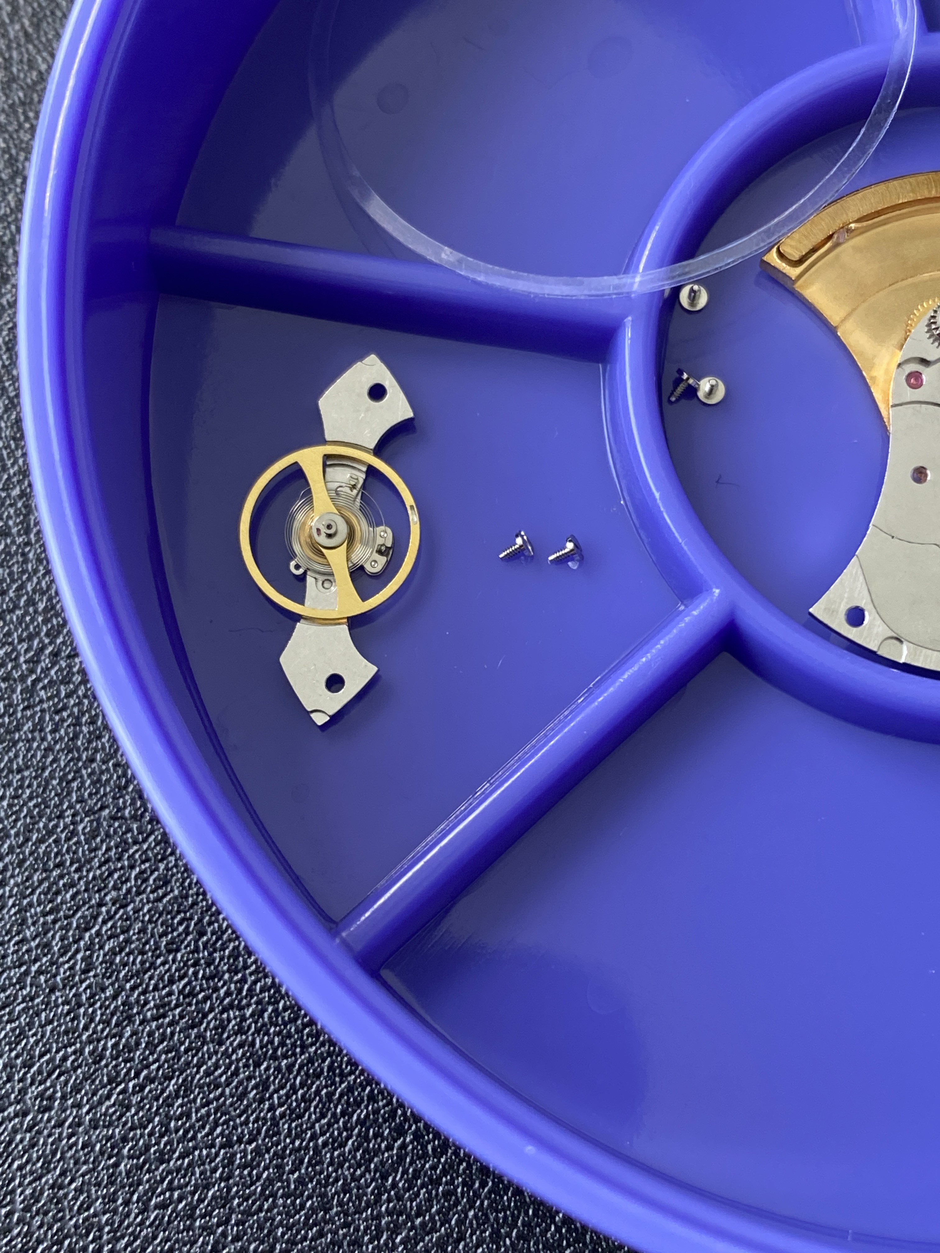
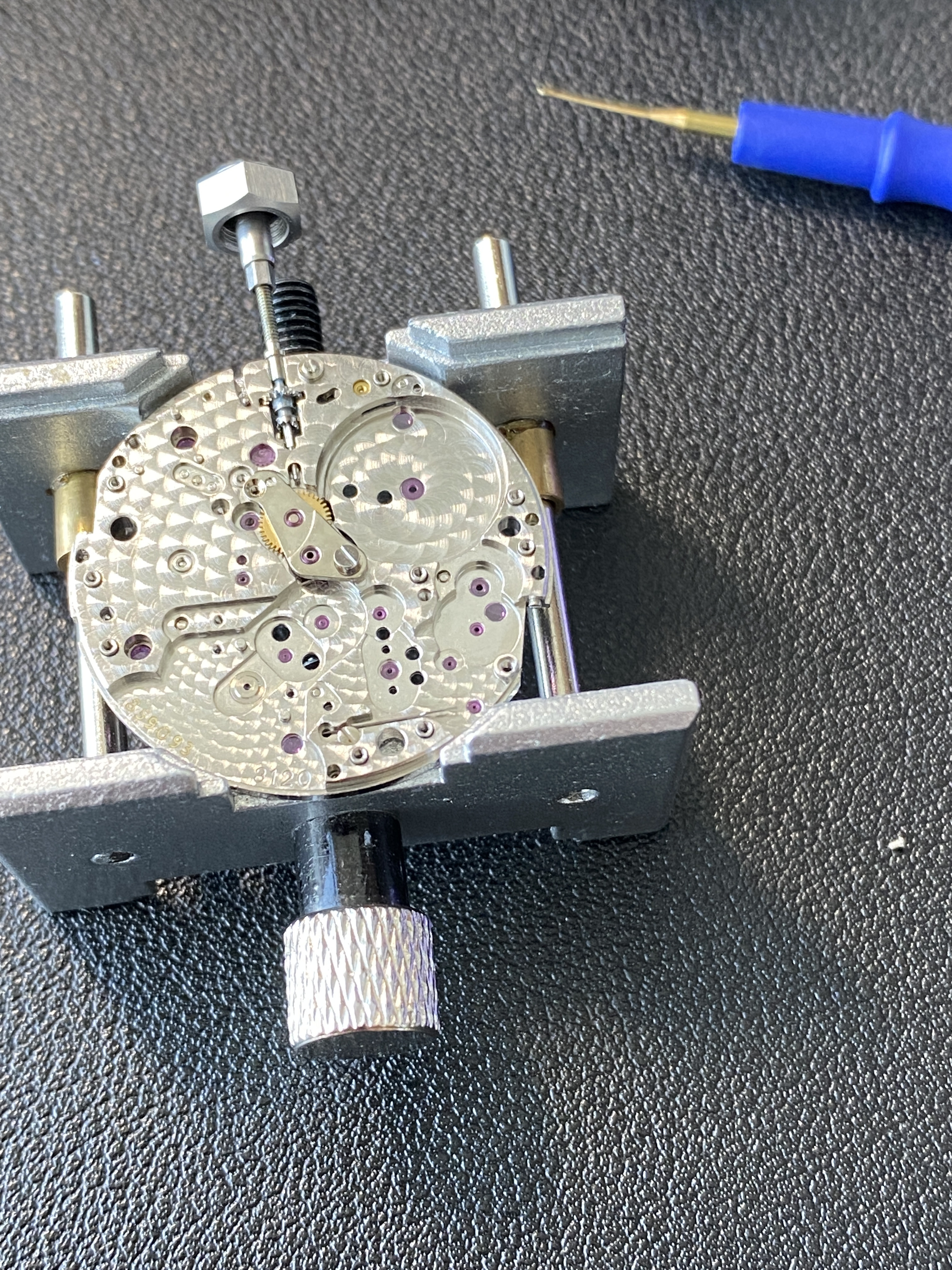
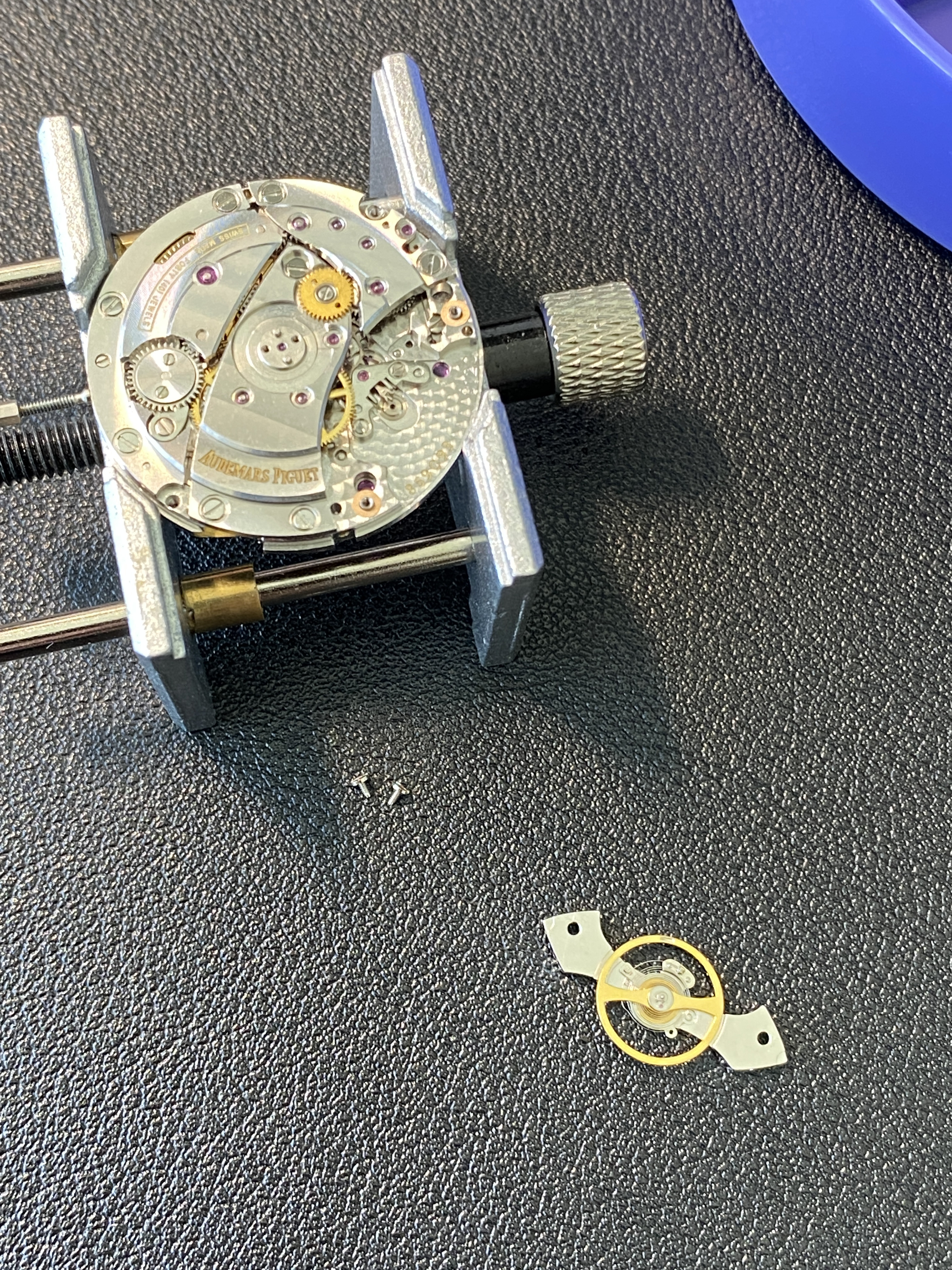
Update: After letting the parts dry under the saran wrap dust cover for an hour, I got to work on the re-assembly. This started with the two sock settings (mercifully there's no shock setting for the escape wheel like there is on the N4130). The two sock settings were much easier to work with than the ones on the N4130 or the VR3235 (or maybe I'm getting better at assembling these tiny bastards). Regardless, I managed to get the two shock settings assembled. I did the balance bridge one first, and I used the mainplate as a jig to hold the balance in place. I figured it would be easier to assemble the setting if if wasn't under tension, so by doing the bridge side first, the balance staff would hang down into the empty setting on the mainplate and allow me to work without upward pressure on the cap jewel. After this was complete, I removed the balance, and worked on the setting in the main plate.

Next was doing an epilame treatment for the keyless works and the automatic module parts. I'm not sure if this is required or recommended, but I'm just kind of cribbing my way along based on what is says to do in the Rolex 3135 movement service manual. This is also the logic I'm using for which lubricants to use in which places as I re-assemble.

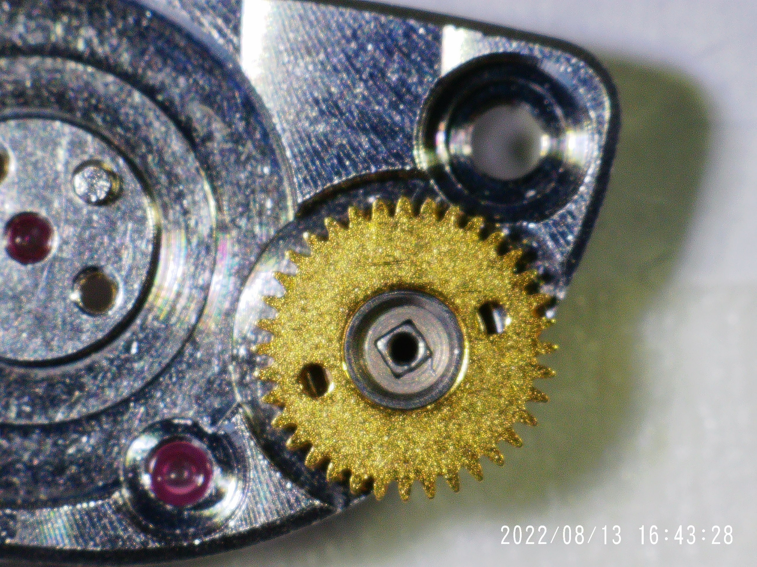
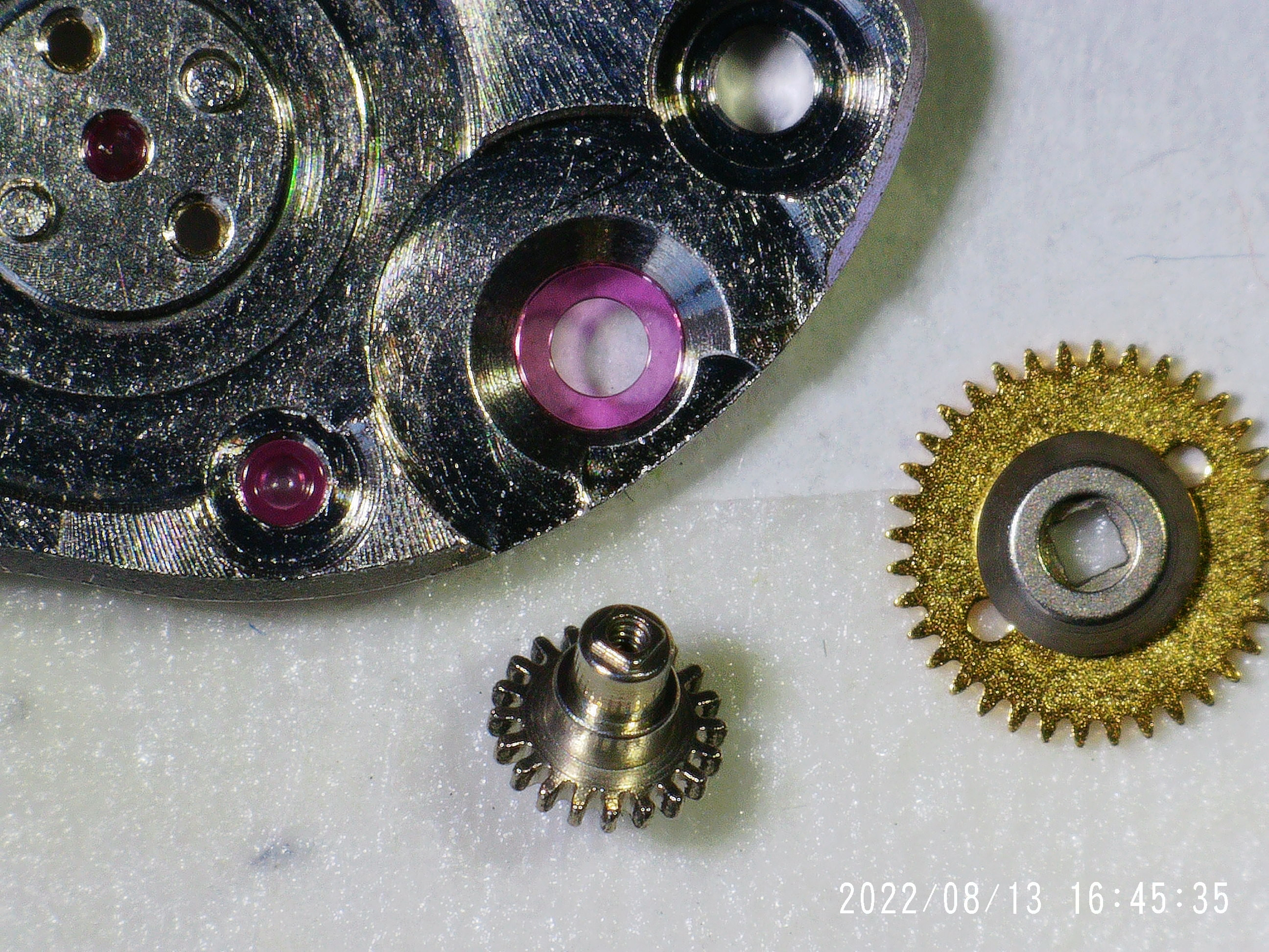
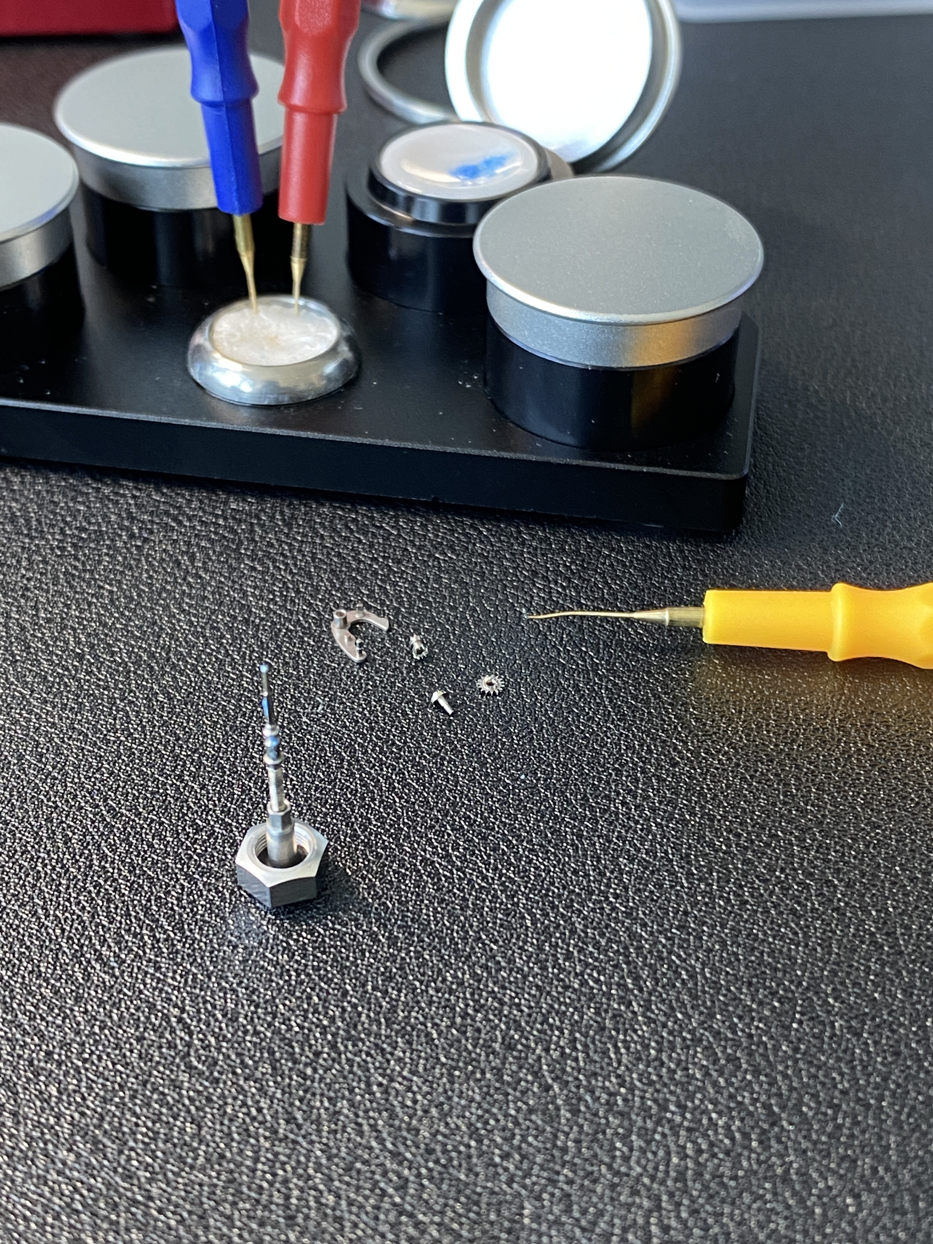
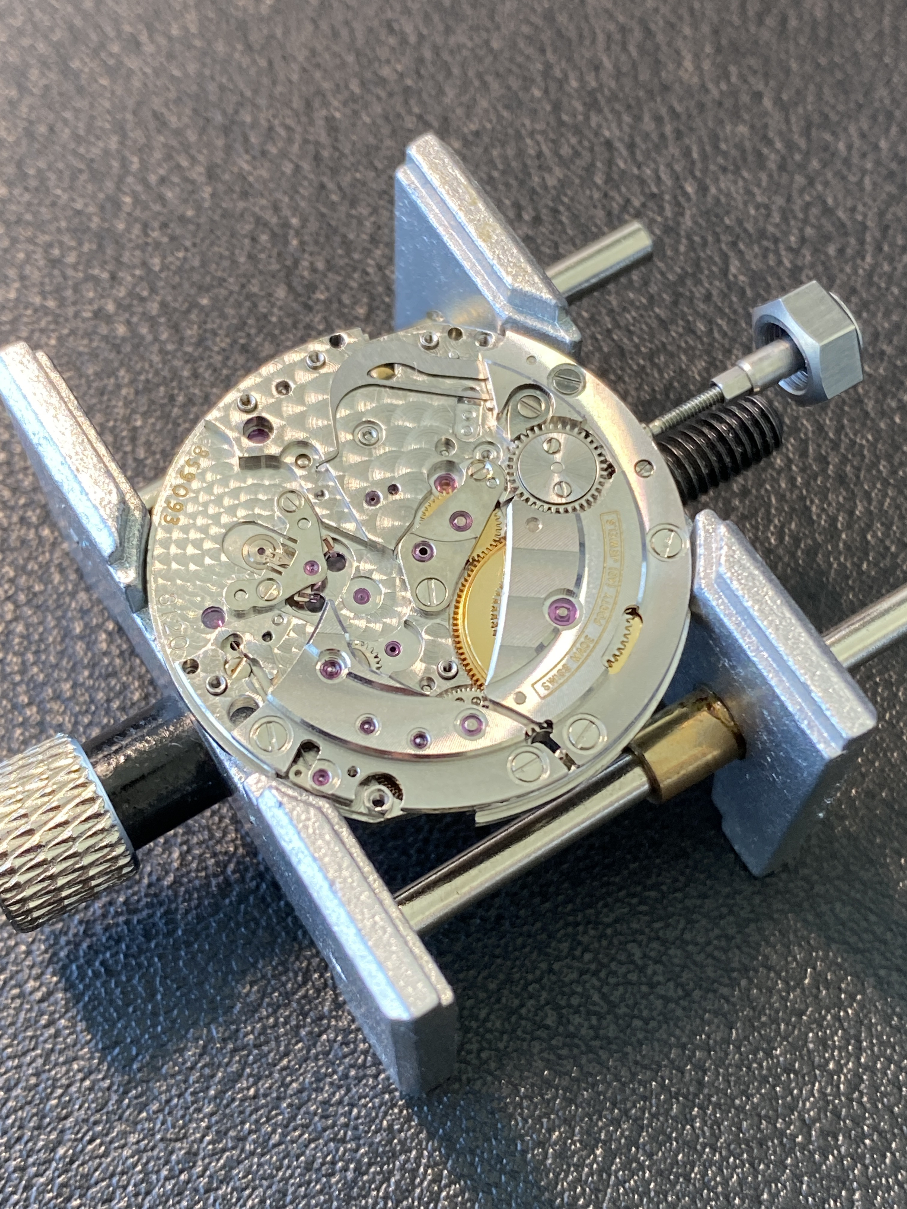
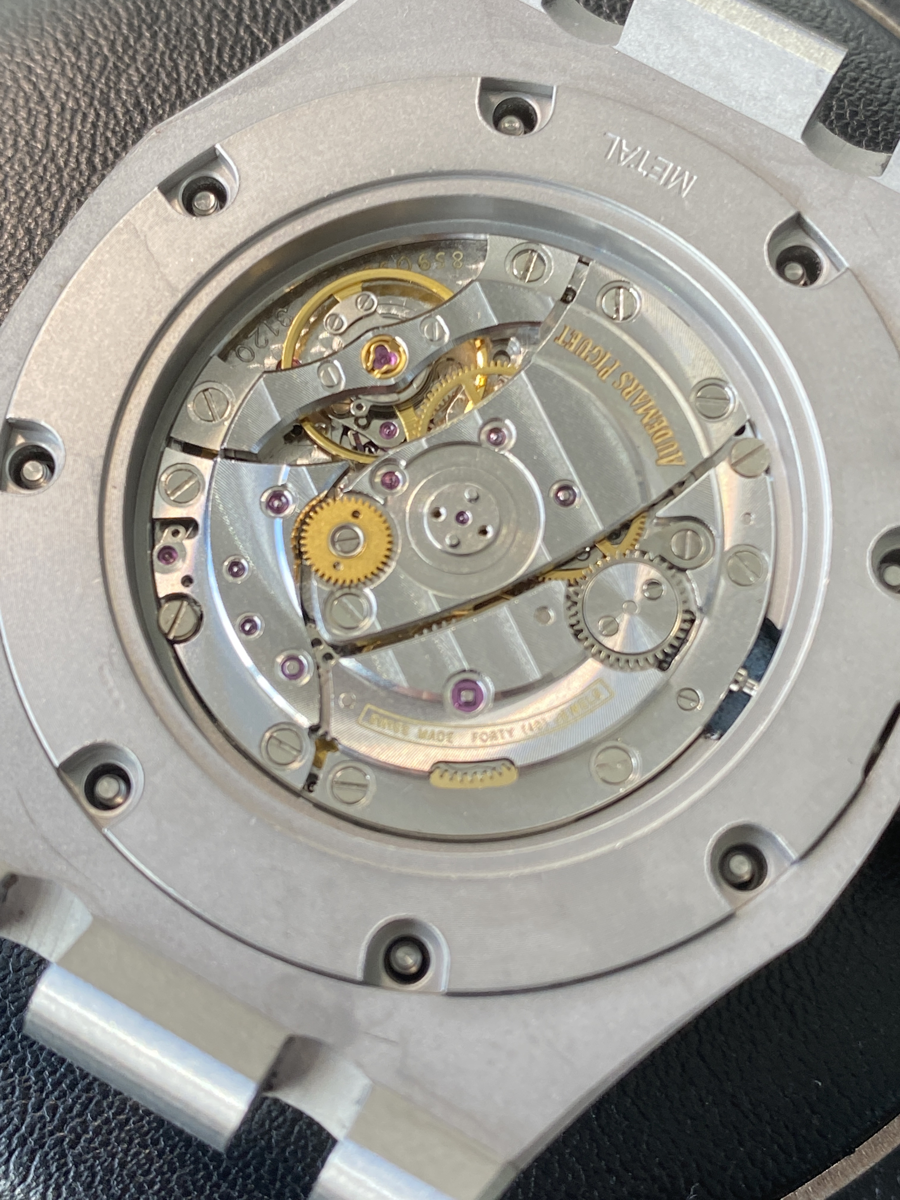
After the epilame was done, I stared re-assembling the keyless works. I started with the yoke and the screw to secure it. I lubricated here with moebius 9415 grease (this grease has a blue dye so it's sometimes visible in the pics). Then I flipped the movement over and installed the stem, winding pinion and sliding pinion. These were also all lubricated with 9415. The 3120 movement has a nice design for this part of the assembly, the mainplate has a slot cut into it, so you can skewer the two pinions on the stem and then place it into the movement and then slide the stem further into its slot. On the rolex caliblers I've worked on, you have to kinda hold the pinion in place on the mainplate and skewer it in place which is more delicate a procedure.

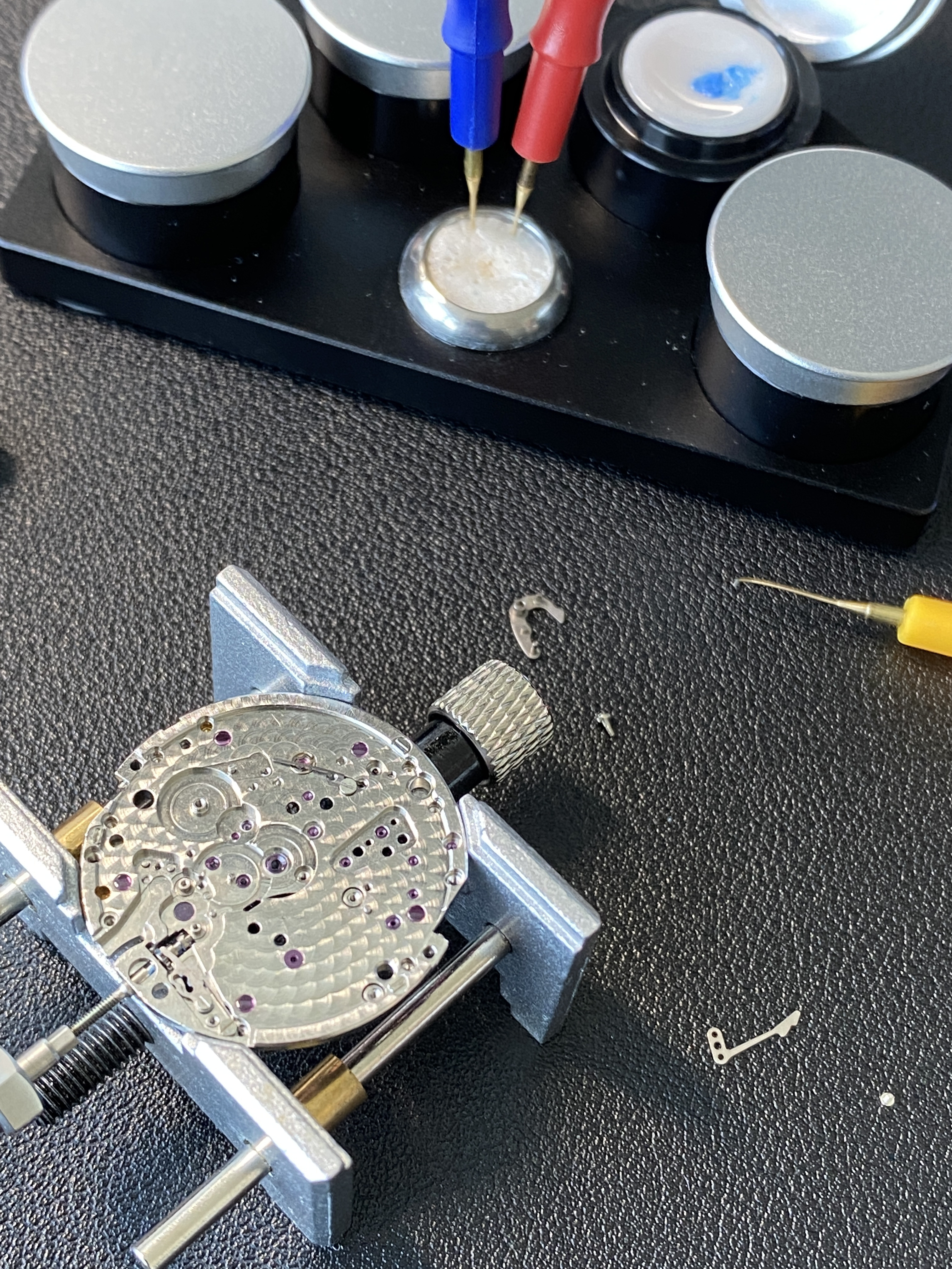
With the yoke, stem, and pinions in place, I flipped the movement again, and installed the setting lever spring. This was a really easy procedure compared to the explosive U-shaped springs found on rolex calibers. All the metal to metal slider surfaces and gently lubricated with 9415.

Then it was on to the setting lever. I was worried that this would be tricky since it's held in place by a screw that threads in from the other side of the movement. But it turns out, that the setting lever, once in place, is held nicely against its pivot by the setting level spring and yoke spring. So there's no danger of it falling away when you flip the movement to secure the setting lever screw from the other side.

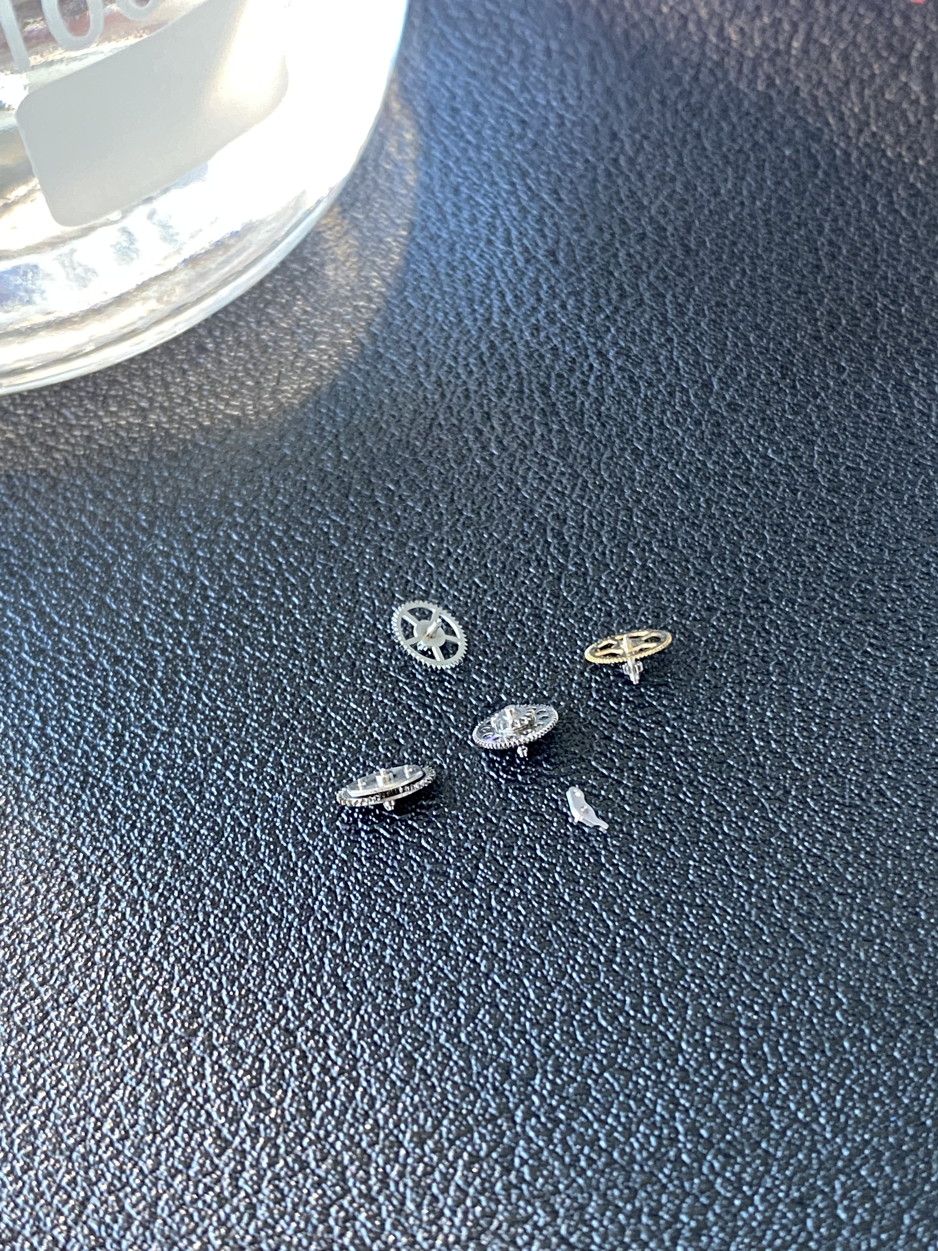
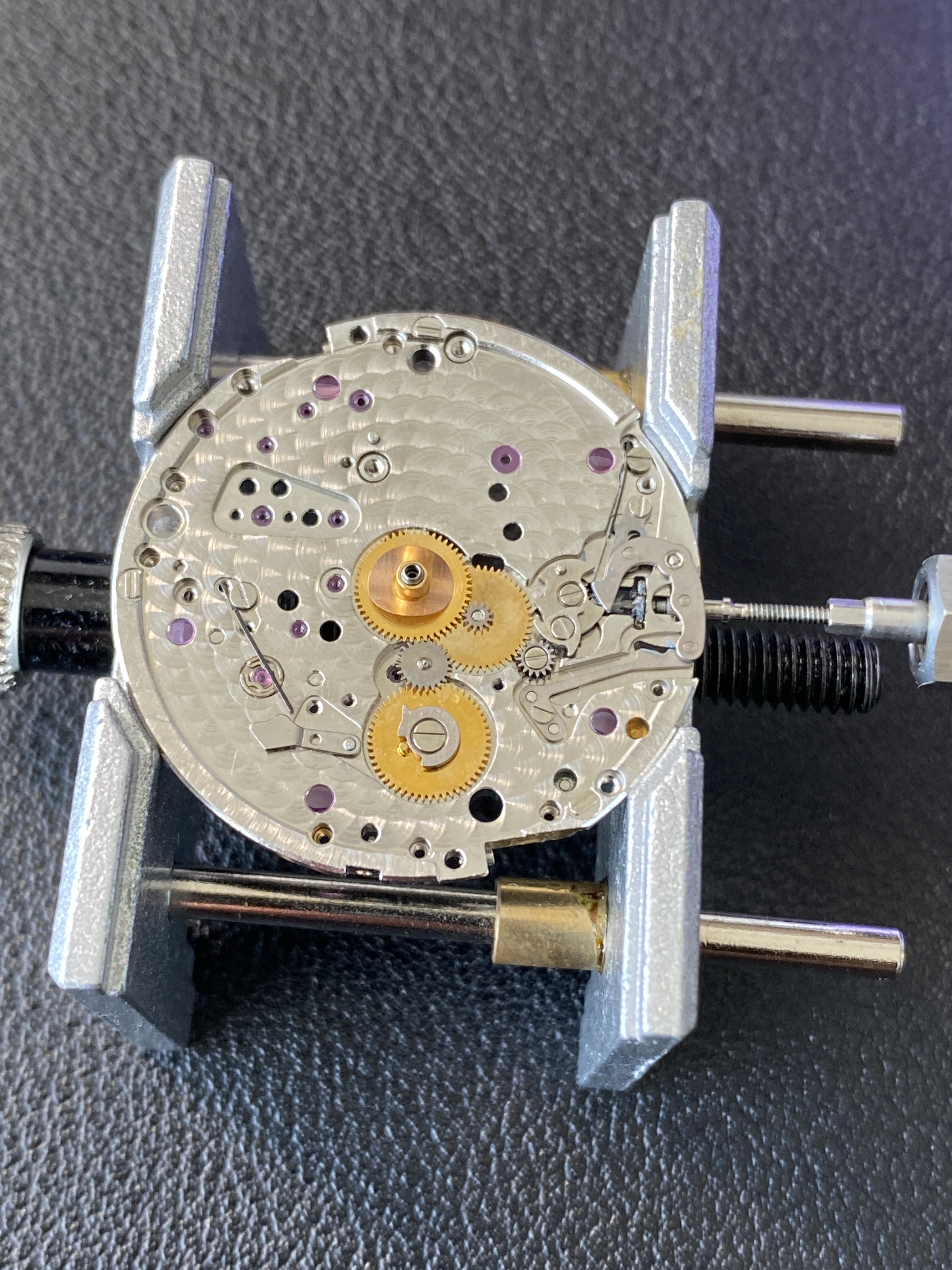
Next was getting all the setting wheels and date quick set wheels back into place. This was pretty straight forward, and made sure to lubricate any columns with 9415 if they had pinions that spun on them. But I used D-5 to lubricate the riveted gear pivots. I'm not sure if this was the correct method, but I figured I wanted an oil to get into the bushing on these parts since I couldn't access them directly with grease.

The it was on to the date change mechanism. Here is used D-5 since I figured there is some fast motion when the date jumps at midnight (well technically it jumps half way because it starts changing at 11pm and gets half way before jumping at 12 midnight). I figured an oil would be better for this type of movement.

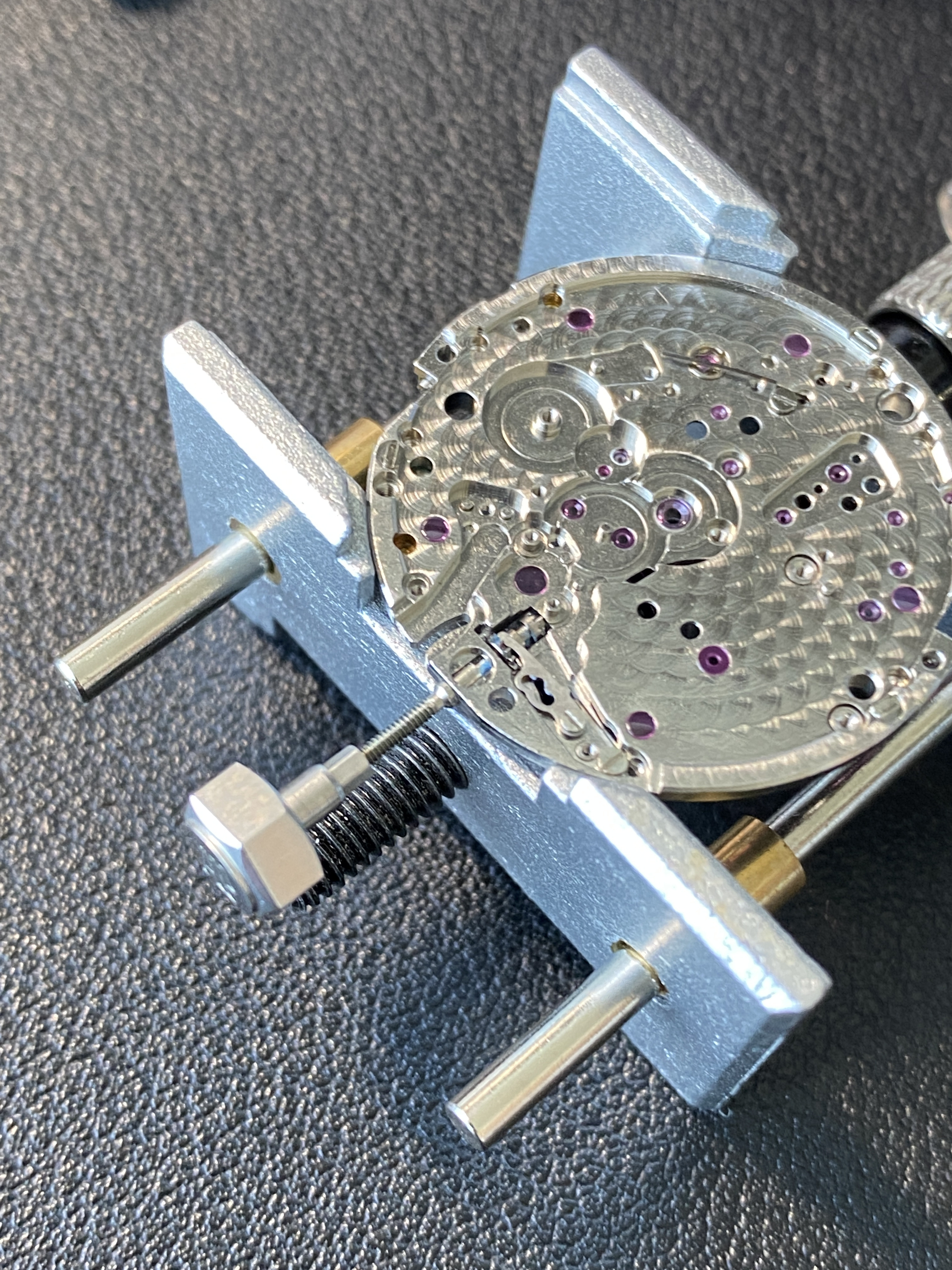
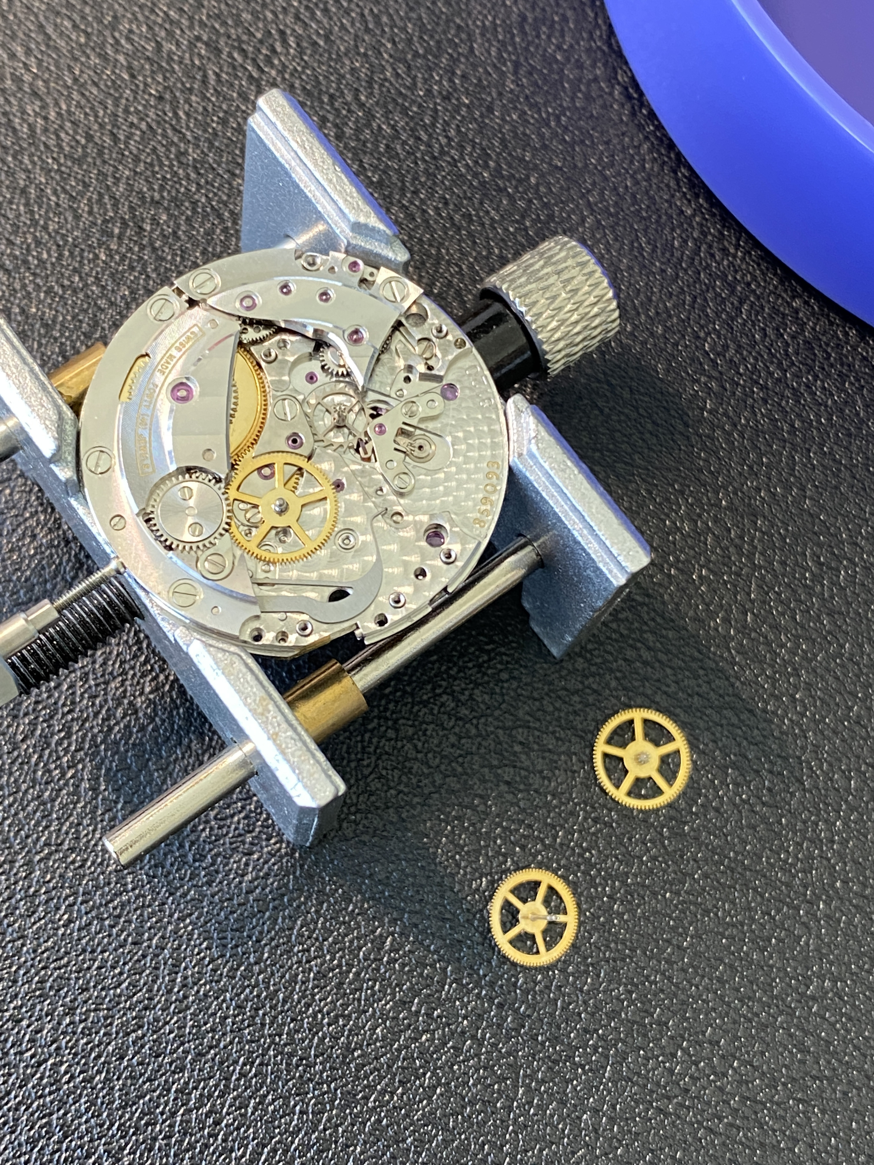
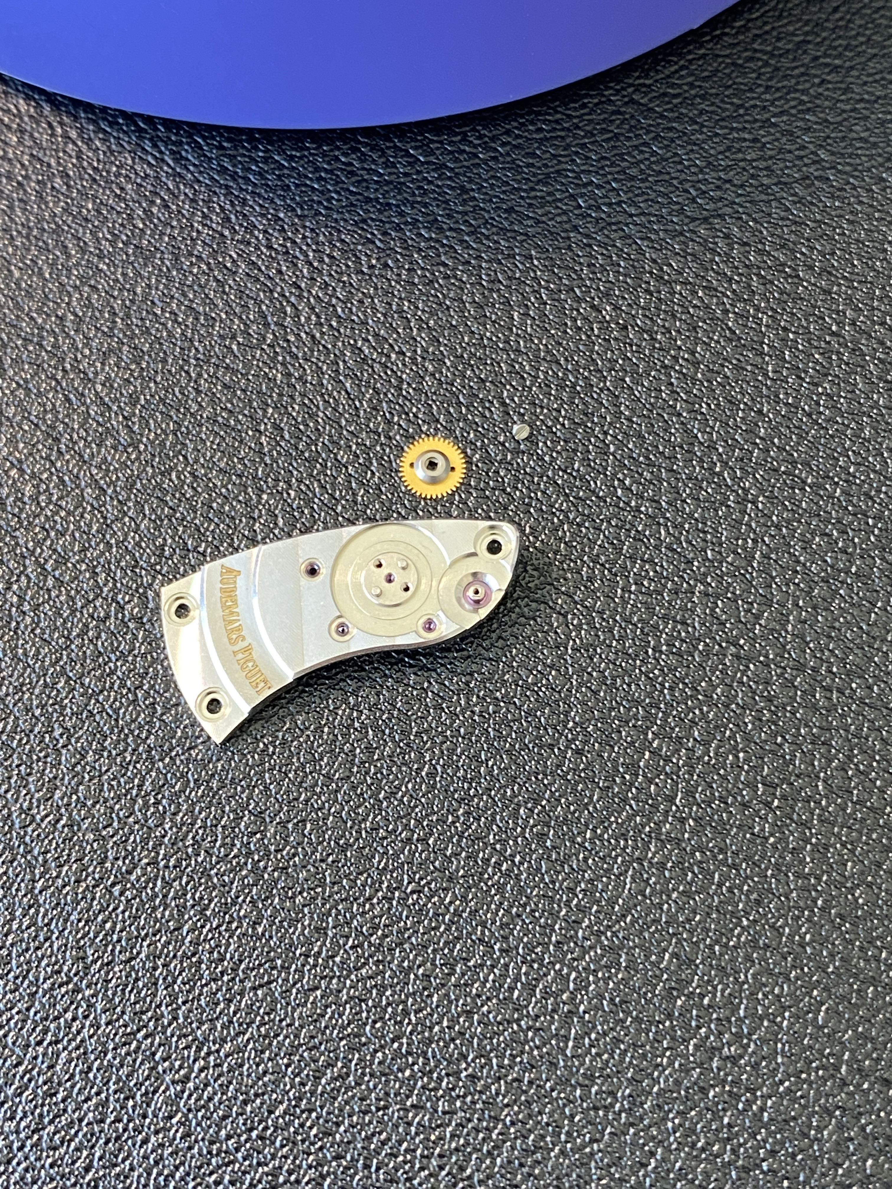
Then I flipped the movement over and installed the minute pinion and the minute pinion bridge. This is where I messed up the order on the disassembly because I removed these parts before removing the cannon pinion / motion works. I lubricated these parts as though they were the parts of a rolex 3135 movement. I'm not sure this was correct, but the design looks very similar in principal, so I'm hoping that D5 in the places I'd put it on a 3135 will work here.

Next I flipped the movement back over to the dial side, and installed the setting intermediate wheel, the hour wheel, and the date intermediate wheel. Here I lubricated with D-5.

And now my back is a little sore, so I think I'll take a walk outside and get some fresh air. Once again, thanks for following along.

zIiKbD.jpg

zIi3os.jpg

zIiHTY.jpg

zIizD3.jpg

zIi25k.jpg

zIiABo.jpg

zIiLNJ.jpg

zIi5KP.jpg

zIiU9W.jpg

zIiiDQ.jpg

zIiWMS.jpg
 

dogwood

I'm Pretty Popular
Patron
Certified
7/9/21
1,901
3,580
113
Canada
Update: So today was about finishing up the assembly of the movement and then regulating it to keep better time than it did before (shouldn't be too hard considering how bad it was before).

I started with the automatic module. This went together pretty easily. Following the instructions for the rolex 3135, the pivots of the automatic module call for D-5 lubrication. I'm not 100% sure this is correct since the automatic modules designs are completely different, so we'll see how this goes in the long run.

Next was the installation of the train of wheels. Again here I lubricated in the same pattern as would be called for in the 3135... that is, D-5 for everything except the escape wheel which gets 9010, and the pallet fork which is not lubricated.

Then I had to assemble to rotor pinion stack that goes through the main train bridge. Recall from my disassembly how I didn't realize the that rotor bridge is also the main train bridge and I exploded the main train wheels because I still have power in the mainspring... lesson learned. Anyway, the rotor pinions screwed together easily, although I wasn't able to tighten the screw with the bridge off of the movement. If I do this again, next time I'll drop the bottom of the assembly into place on the main plate, then put the bridge on, secure it, and then place the top part of the rotor pinion assembly in place and screw it down. I did need to hold the top (brass) rotor pinion with a pegwood to make sure I could fully tighten the screw.

Then it was installing the balance complete. This was relatively easy. Although again, unlike the rolex caliblers I've worked on before, there's no easy way to adjust for endshake other then little brass shims that can be used to lift the balance bridge. I re-used the two shims that came with the movement, and I think my end shake is about correct. However, this is something to be aware of, if you service this movement, you might need to make some shims out of aluminum foil if you re-assemble and need to increase end shake.

Then it was on to regulation. It turns out that even though the true regulator arm is kinda hidden under the balance bridge, there's an additional arm (the one on the inside of the balance bridge with a little hole in the end of it), which is connected to the regulator arm. This allows for easy regulation even if the true regulator arm is under the bridge. Regulation is very sensitive, so it took me a little bit of back and forth to get it dialed in. I also found that even after my service, there was still a ripple on the time grapher. My guess is that this is due to geometry of the escape wheel. It looks like gen AP 3120 / 3126 escape wheels can be found on places like EBay for around $200. I don't love my AP RO as much as I love my Daytona and Sub, so I don't think I'm ready to do a franken movement yet... but in the future it would be interesting to see which gen parts are drop in compatible with the clone 3120 movement.

And of course, here are some pics:

zIYxd4.jpg

zIYJJI.jpg

zIYcWc.jpg

zIYglX.jpg

zIyDFi.jpg
 

dogwood

I'm Pretty Popular
Patron
Certified
7/9/21
1,901
3,580
113
Canada
So after a bit more playing around with the movement, I noticed that it often wouldn’t start itself back up after I hacked the movement. Also, the amplitude was quite a bit lower than the ~280 range before I did the service. I thought that since I did open up the shock settings, the problem might be the balance staff end shake. Unfortunately, there’s no screw adjustment for balance bridge height, so I was left with making shims out of aluminum foil. I used a double thickness (one fold) piece on one end and a triple thickness (double fold) on the other. Amplitude increased nicely and the movement starts easily after hacking.

zI114F.jpg
 
  • Like
Reactions: centrum and heska

dogwood

I'm Pretty Popular
Patron
Certified
7/9/21
1,901
3,580
113
Canada
Conclusion. So it turns out that re-casing the ZF AP 15400 is a huge pain in the ass. But we'll get there...

First was getting the dial back on. No problem since the three pieces of doubled sided tape were still sticky, so I simply placed the dial back onto the movement, being sure to line up the date window and cannon pinion. Next, the hands went on easily enough, but then it came time to get the movement back into the case. There was a white / transparent looking gasket thingy that goes between the back of the dial and the case, I think this is supposed to also be an adhesive to keep the dial from falling forward. The reason there's this adhesive is because in addition to not using dial feet, ZF also didn't use case clamps!!!!! There are threaded mounts for both dial feet and case clamps on the movement, but ZF elected to save on the cost of four screws, two feet, and two case tabs. I get it times are tough all around, but for a premium rep I expected a little more effort. Come on ZF, level up your game!

I didn't have any spare case clamps on my bench (going to have to order an assortment of them now!) but I was able to improvise with some large headed screws (visible in the 5th pic but missing in the 4rd). I also made sure to lubricate all the O-rings and gaskets (pic 3 and 6).

And of course what project would be complete without a wrist shot to finish the job. Thanks everyone for following along. I hope this thread is useful if you decide you want to service the clone 3120 movement yourself.

zI9oXP.jpg

zI9OUS.jpg

zI9YQQ.jpg

zI9qxW.jpg

zI9yfL.jpg

zI99hR.jpg

zI9nn8.jpg
 

centrum

Active Member
27/7/14
442
187
43
You're doing God's work mate. What a journal. We need more guys like you on this forum! 👍

It seems that the clone 3120 is difficult to play with. Are there any advantages going with going with this watch compared to Miyota versions?

How's the build quality of this movement compared to VR 3135 which is a decent clone movement.