These are pictures/step by step of me taking apart and reassembling the keyless works on an ETA 2836-2. I'm by no means an expert, just starting to learn this stuff. If I did something wrong, someone please let me know. I will edit the post to reflect that.
I didn't intend on doing a step by step initially, so I didn't take all that many/great pictures. I am having to use mostly the reassembly pics for both the disassembly and reassembly. Next time I do one (on an a7750 which should be in the next couple weeks), I will certainly take better pics.
This particular ETA 2836-2 is a little bit of an oddball. It is in an older Sandoz Datejust. It has no balance stop (hack) lever. When I decided to take it apart, I thought it just was bent or something, but as far as I can tell, this one never hacked (someone please correct me if I'm wrong, I don't know much about the different versions of these). It also has no day wheel installed. So removing/reinstalling that is an extra step on any movement with a day wheel.
I start out with the movement uncased, hands removed, and dial removed. There are other step-by-steps on how to do that, I believe.
STEP 1:
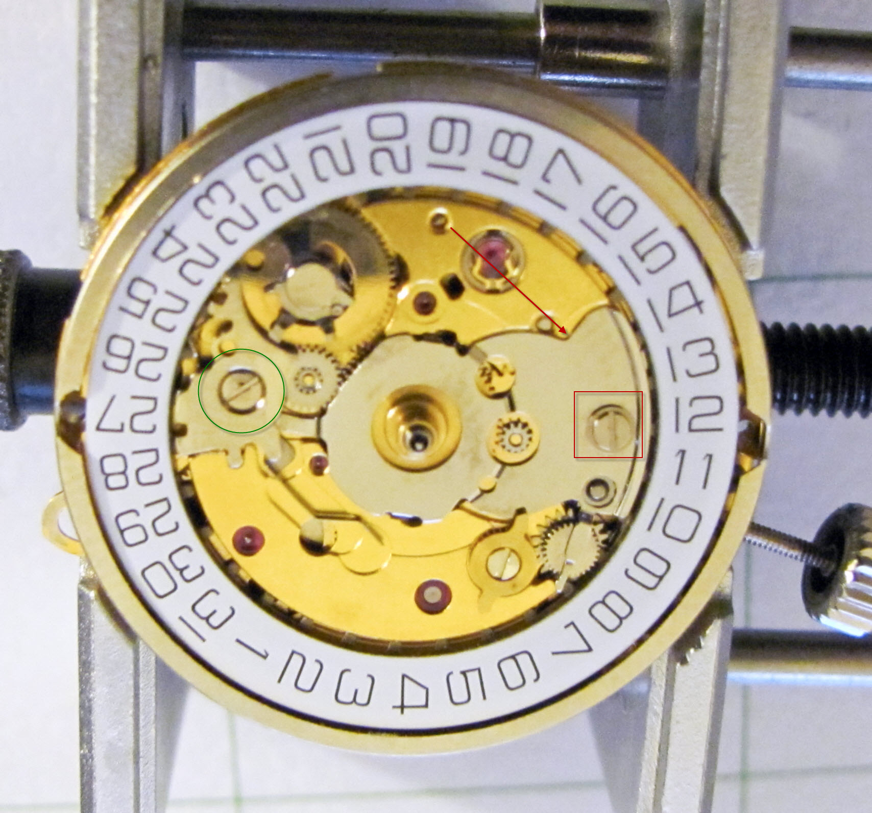
On this first step I loosened the screw circled in green. I then removed the screw that is circled in red. Then I remove the entire plate that is pointed to in red. Loosening the green circled screw makes it easier to remove the plate, because the plate has a tab that sticks underneath it.
STEP 2:
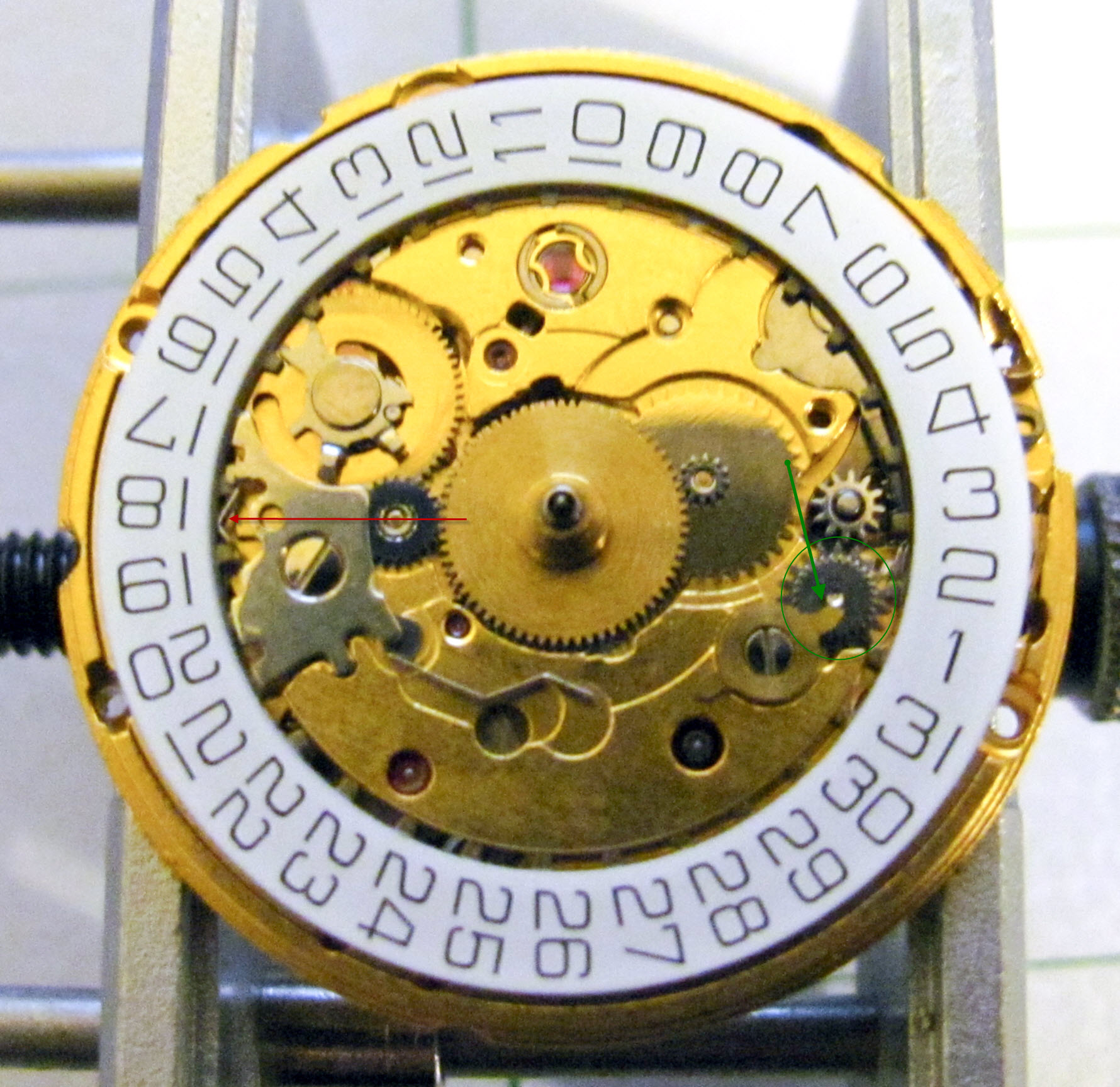
In this step, I remove the day wheel. I do this by sliding it slightly to the left and just lifting it off. The plate that was previously removed held it on. I slide it to the left a little bit, because it is also underneath a plate slightly where the red arrow is pointing.
I also remove the gear circled in green. The tab that the green arrow points to, is part of the day mechanism which is not on this watch. It can simply be pushed out of the way to remove the gear.
STEP 3:
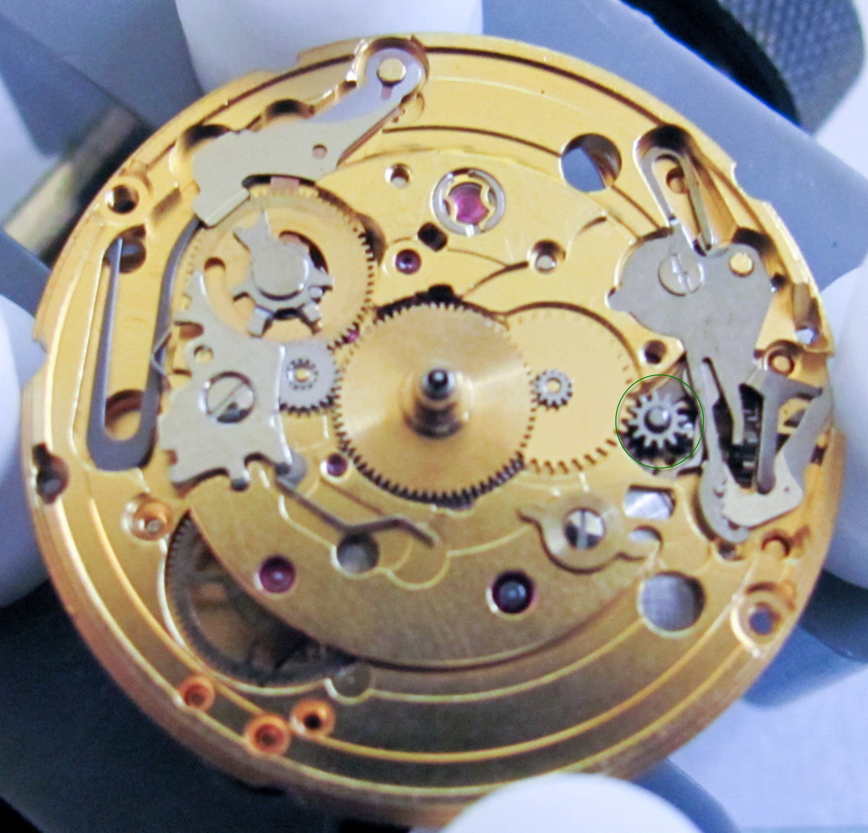
This is a simple step. I remove the circled gear (set wheel).
STEP 4:
I now remove the screw that is in the red square and then lift off the keyless works cover plate that is pointed to.
STEP 5:
I then remove the lever (Clutch return) that is pointed to in this picture.
STEP 6:
The next step is to remove the next lever (set lever), which is pointed to.

STEP 7:
Again, I remove a lever (double corrector operator) that is pointed to. Sorry for the bad pic.

STEP 8:
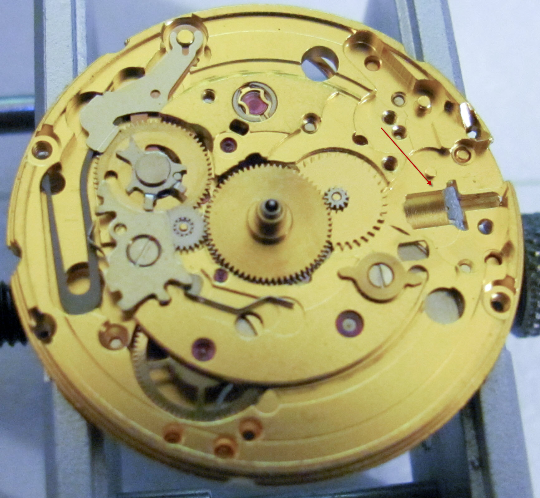
Then, I remove the clutch (the red arrow points at the clutch) and the winding pinion (the winding pinion is the gear to the right of the clutch). I forgot to get separate pictures of these two parts and apologize for that.

STEP 9:
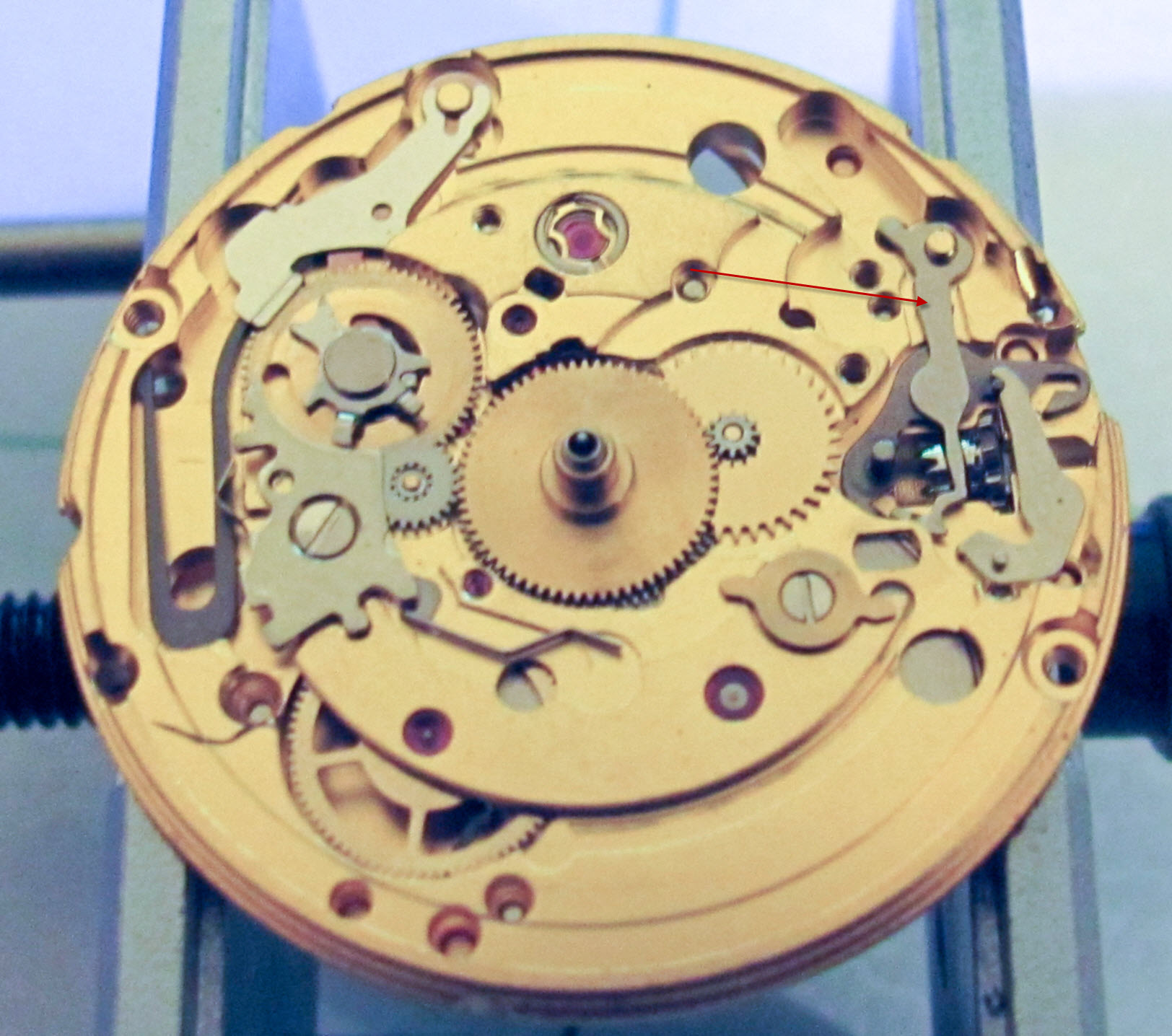
This is just a picture of the half way point. The keyless works have been removed. An interesting note (think back to the intro) on this particular movement is the lack of a hacking/balance stop lever. If there were one, the foot of it would be sticking out into the valley where the red arrow is pointing. The balance stop lever would be set into the groove in the clutch and would basically be moved by the clutch so the other end stops the balance when the clutch is pulled out by the crown.
Step 10:
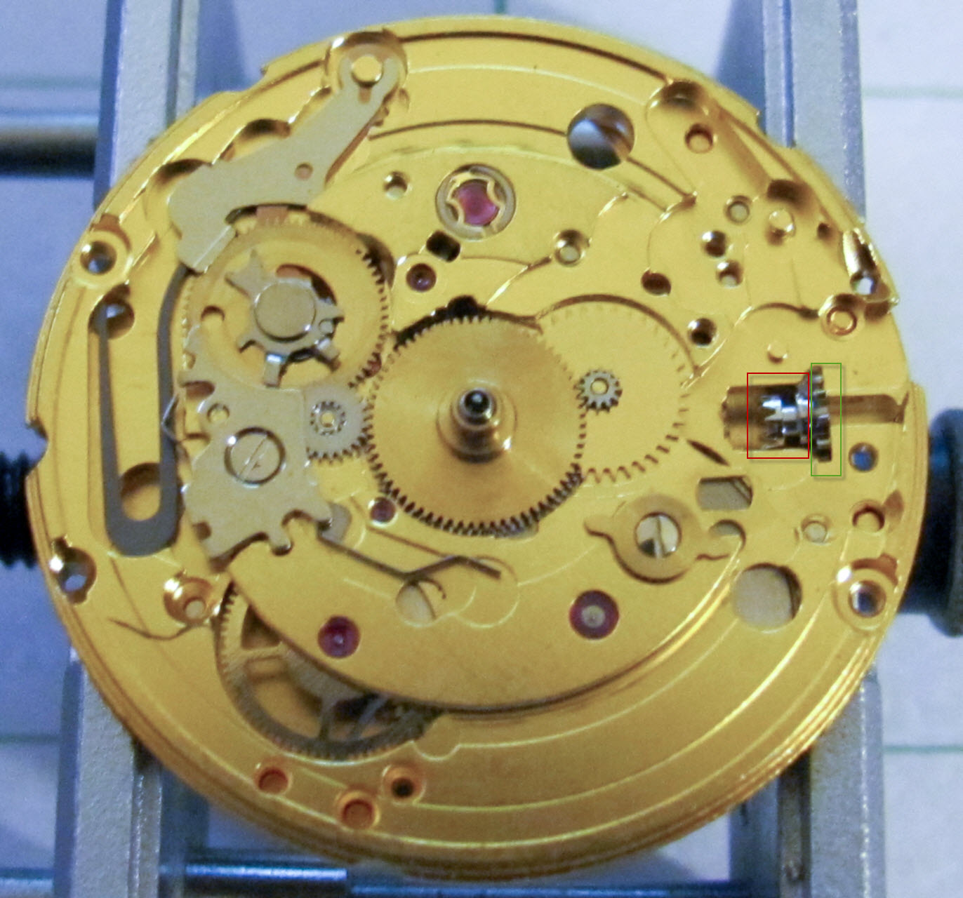
Next, I put in the clutch (red box) first and then the winding pinion (green box). The gears of the winding pinion should mesh/interact with the gears of the clutch appropriately. NOTE: If you have a balance stop (hacking) lever in your movement, you will want to make sure the foot of it sets in the groove in the middle of the clutch.
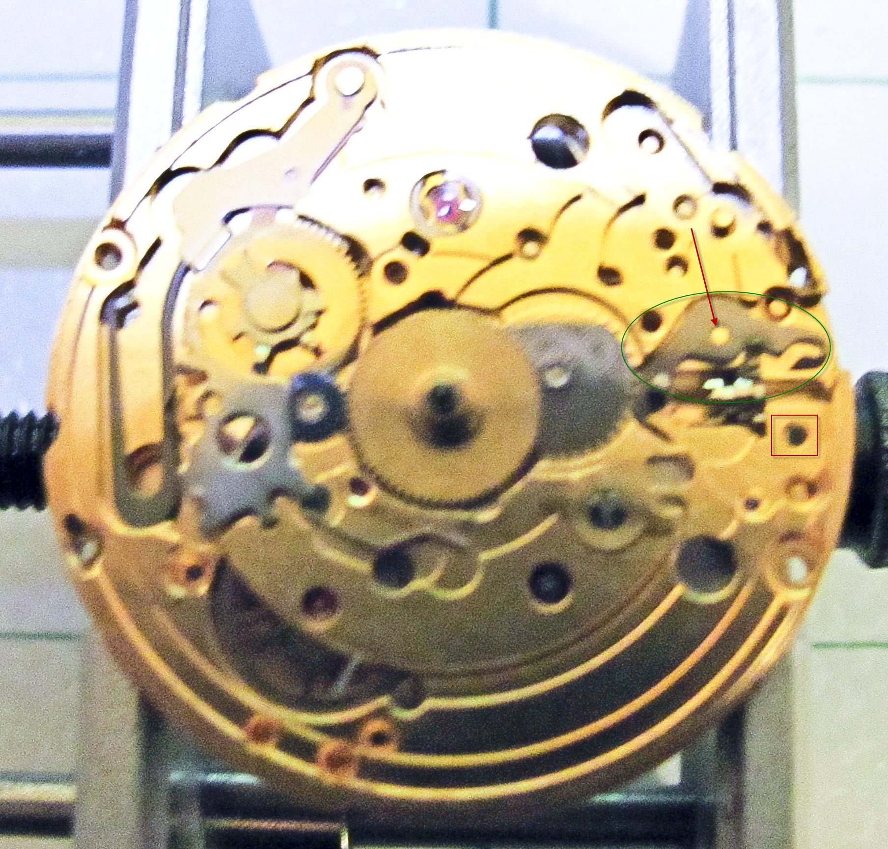
Step 11: Next I replace a lever (the double corrector operator lever) which is circled in green. Notice that the hole in the lever sits on the post that is pointed to with the red arrow. Also note the hole that is marked by the red box. The post on the next lever to be installed will sit into that hole.
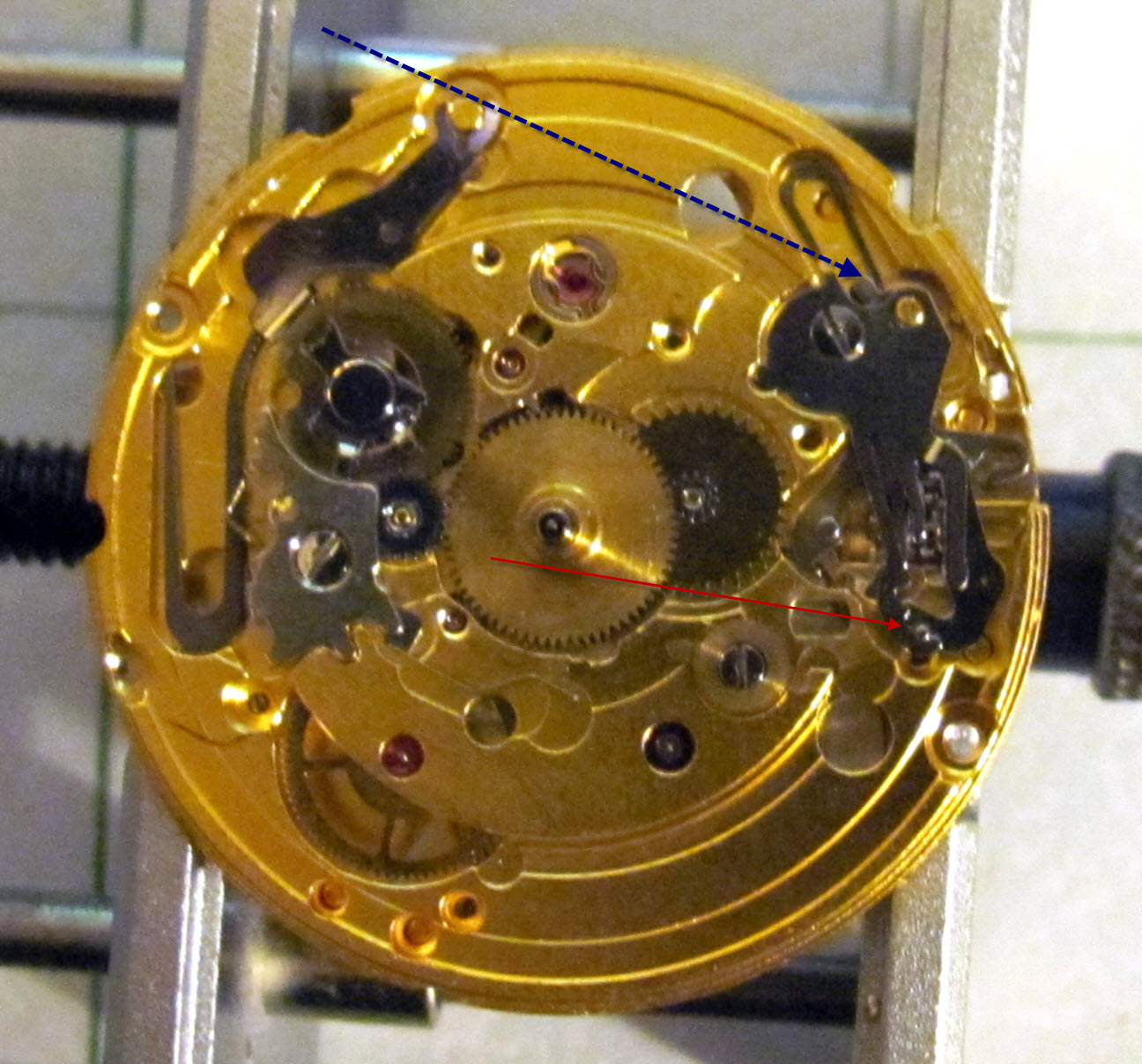
Step 12: Next, I place another lever (the set lever) which is circled in green. The post on the bottom of the set lever, sits into the hole in the bottom plate that was marked by the red square above. The red arrow in this picture points to the location of the post/hole. The blue arrow in this picture points to the interaction between the post on the top of the double corrector operating lever and the set lever. You want to make sure that they are touching like shown in the picture.
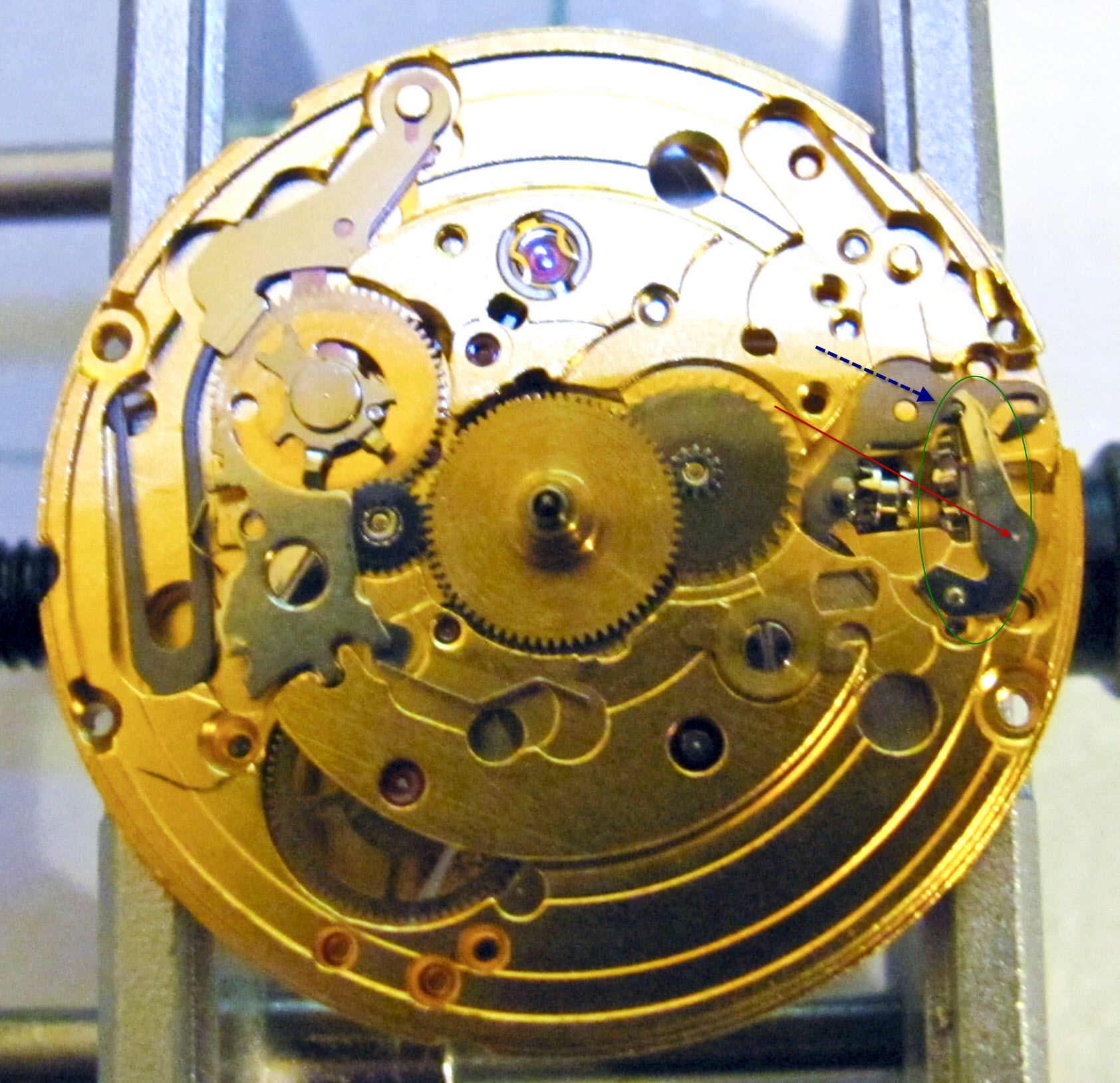
Step 13: Next, I place another lever (the clutch return) which is circled in green below. The hole in the clutch return sits on the post that the red arrow points to. Also, be sure that the narrow part of the lever sits into the clutch. I should have made an arrow to this, but forgot to. Take note of the post that the green arrow points to, and the top of the clutch return that is pointed to by the blue arrow. Those will be used in the next step.
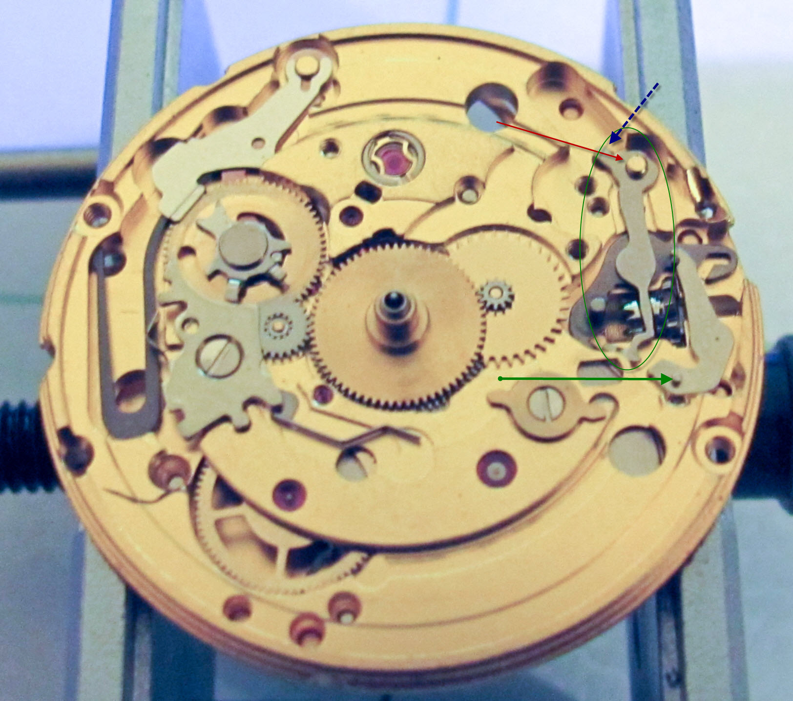
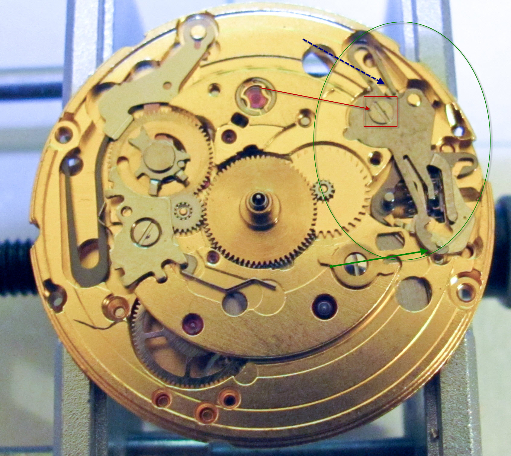
Step 14: This step is a little more complicated. First, I place the keyless works cover plate (circled in green) as shown. Then I screw in the screw that is pointed to with the red arrow and inside of the red square. I screw it in so it is tight, but without stripping it. Now, you need to make sure that the cover plate interacts with the post on the set lever (green arrow) and the top of the clutch return (blue arrow). IN THE PICTURE, the interaction with the set lever is fine, but THE INTERACTION WITH THE CLUTCH RETURN IS NOT CORRECT IN THE FIRST PICTURE The top part of the keyless works cover needs to be pushed over with a small screw driver, or piece of nylon, so that it acts as a spring on the top right side of the clutch return. The second picture below shows the correct positioning for this piece. After this is done, its a good idea to blow off any dust or particles and wipe fingerprints/smudges off with Rodico. I don't do that before, because the levers will fly out or get dislodged.
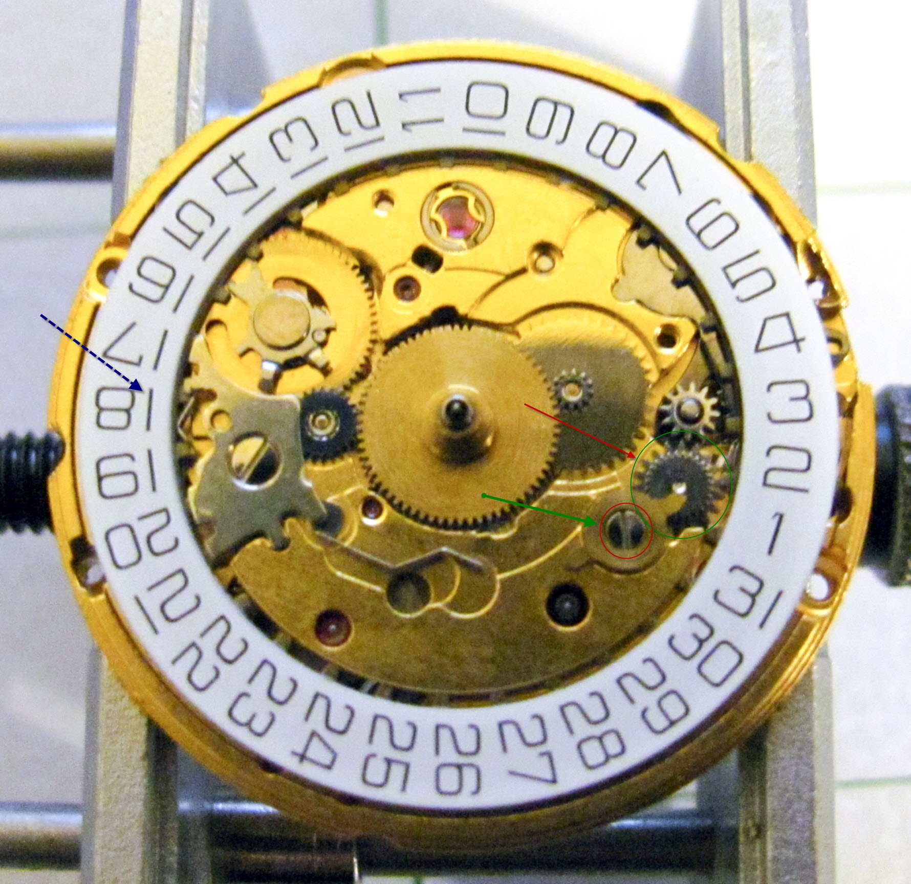
Step 15: I then place the circled gear (set wheel) on the post as shown. I have also circled and pointed to a hole in green. Remember this hole for the next step.
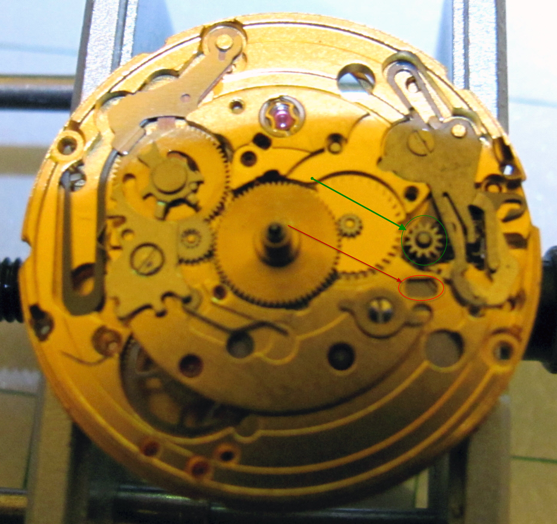
Step 16: Next I install the gear (double corrector) circled in green below with a red arrow pointing to it. The post on the bottom of it, sticks into the hold that was circled in green above. The wider side of the wheel goes down. I then moved the tab circled in red over the double corrector, to hold it in place so I don't dislodge it during the next steps. This tab is part of the day mechanism, which this particular version of the 2836-2 doesn't have installed. If you have a day mechanism, you will need to make sure this tab is installed correctly for that mechanism (I would look at the eta breakdown if you have them available). Finally on this step, I set the date wheel on a little to the left of where it will end up. I set it on to the left and then slide it over to the right. If you look at the blue arrow, that points to the date jumper and the plate that protects it. The date wheel should slide so that its gears are interacting with the jumper and slightly under part of the plate. I would then again, wipe everything off with rodico.
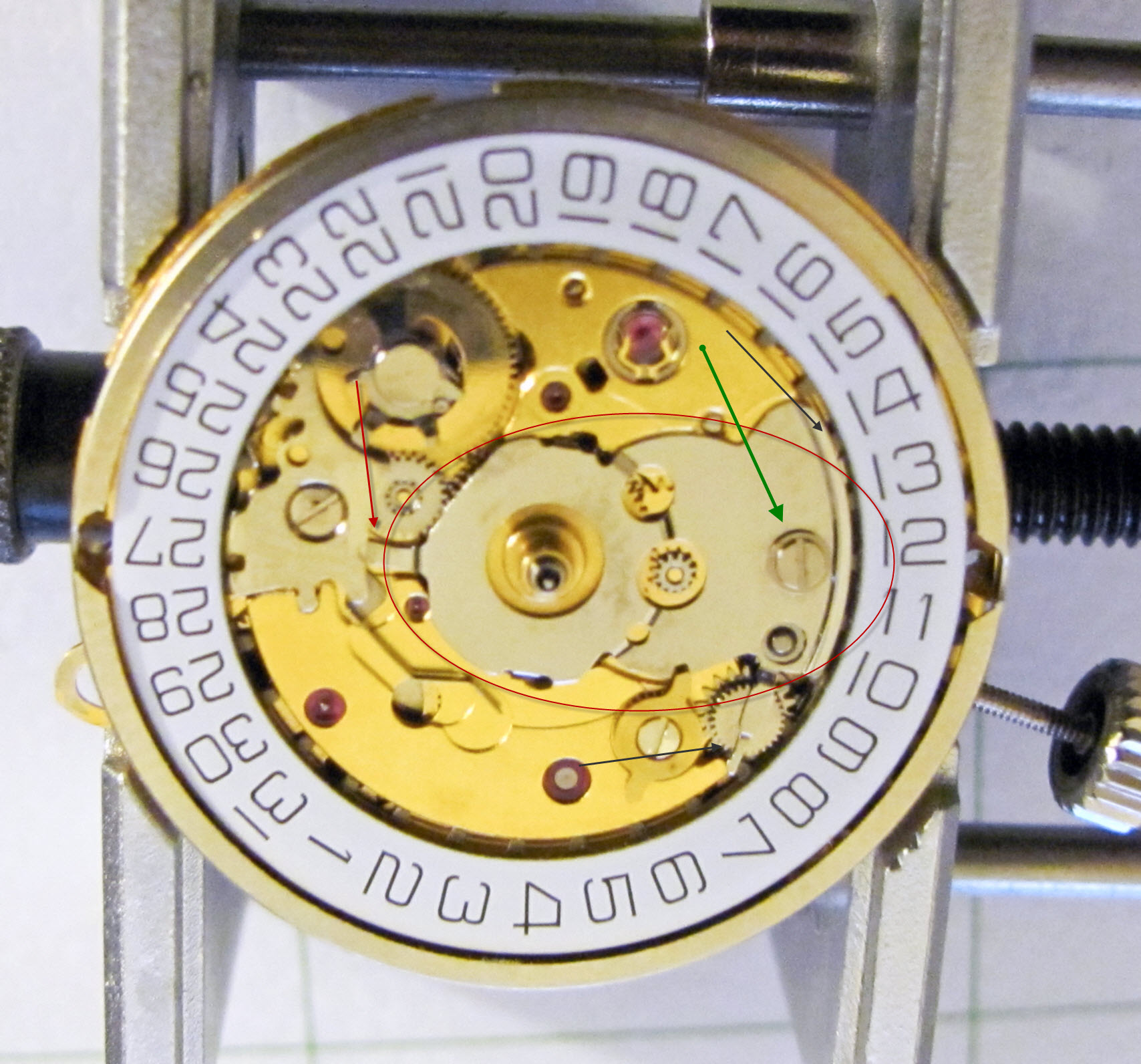
Step 17: In this step I place the plate (minute cock) on the movement, which is circled in red. The right edge of it holds on the date wheel (black arrow). To the far left, a tab has to stick under the minute jumper plate. On the bottom right, a tab sets over the double corrector (the lower black arrow). I found this was easiest to put on by setting it in place so the tab went under the minute jumper plate, but so that the other end of the minute cock was a little bit below (in the picture) where it should be. I then pushed it up into place and installed the screw that the green arrow points to and tighten that screw. As a final step, I tightened the screw on the minute jumper plate (Circled in green in the very first picture) that I had loosened in the first step and then blow off/wipe off smudges and fingerprints again.
STEP 18: Now, you can put in the stem and crown and make sure everything sets and adjusts correctly. This will save you the trouble of having to remove the dial and hands if something is wrong and you reinstalled them without checking. After checking the winding, date change, and time set functionality, make sure to adjust the time forward just until the date changes. Stop immediately when it the date does change. Also make sure the balance is stopped after you do this (for this movement I used a little rodico on the balance because it has no hack). This will ensure that when you reinstall the dial and hands at 12:00 that the date will change at midnight instead of 11:30 or some other random time.
I didn't intend on doing a step by step initially, so I didn't take all that many/great pictures. I am having to use mostly the reassembly pics for both the disassembly and reassembly. Next time I do one (on an a7750 which should be in the next couple weeks), I will certainly take better pics.
This particular ETA 2836-2 is a little bit of an oddball. It is in an older Sandoz Datejust. It has no balance stop (hack) lever. When I decided to take it apart, I thought it just was bent or something, but as far as I can tell, this one never hacked (someone please correct me if I'm wrong, I don't know much about the different versions of these). It also has no day wheel installed. So removing/reinstalling that is an extra step on any movement with a day wheel.
I start out with the movement uncased, hands removed, and dial removed. There are other step-by-steps on how to do that, I believe.
STEP 1:
On this first step I loosened the screw circled in green. I then removed the screw that is circled in red. Then I remove the entire plate that is pointed to in red. Loosening the green circled screw makes it easier to remove the plate, because the plate has a tab that sticks underneath it.
STEP 2:
In this step, I remove the day wheel. I do this by sliding it slightly to the left and just lifting it off. The plate that was previously removed held it on. I slide it to the left a little bit, because it is also underneath a plate slightly where the red arrow is pointing.
I also remove the gear circled in green. The tab that the green arrow points to, is part of the day mechanism which is not on this watch. It can simply be pushed out of the way to remove the gear.
STEP 3:
This is a simple step. I remove the circled gear (set wheel).
STEP 4:
I now remove the screw that is in the red square and then lift off the keyless works cover plate that is pointed to.
STEP 5:
I then remove the lever (Clutch return) that is pointed to in this picture.
STEP 6:
The next step is to remove the next lever (set lever), which is pointed to.
STEP 7:
Again, I remove a lever (double corrector operator) that is pointed to. Sorry for the bad pic.
STEP 8:
Then, I remove the clutch (the red arrow points at the clutch) and the winding pinion (the winding pinion is the gear to the right of the clutch). I forgot to get separate pictures of these two parts and apologize for that.
STEP 9:
This is just a picture of the half way point. The keyless works have been removed. An interesting note (think back to the intro) on this particular movement is the lack of a hacking/balance stop lever. If there were one, the foot of it would be sticking out into the valley where the red arrow is pointing. The balance stop lever would be set into the groove in the clutch and would basically be moved by the clutch so the other end stops the balance when the clutch is pulled out by the crown.
Step 10:
Next, I put in the clutch (red box) first and then the winding pinion (green box). The gears of the winding pinion should mesh/interact with the gears of the clutch appropriately. NOTE: If you have a balance stop (hacking) lever in your movement, you will want to make sure the foot of it sets in the groove in the middle of the clutch.
Step 11: Next I replace a lever (the double corrector operator lever) which is circled in green. Notice that the hole in the lever sits on the post that is pointed to with the red arrow. Also note the hole that is marked by the red box. The post on the next lever to be installed will sit into that hole.
Step 12: Next, I place another lever (the set lever) which is circled in green. The post on the bottom of the set lever, sits into the hole in the bottom plate that was marked by the red square above. The red arrow in this picture points to the location of the post/hole. The blue arrow in this picture points to the interaction between the post on the top of the double corrector operating lever and the set lever. You want to make sure that they are touching like shown in the picture.
Step 13: Next, I place another lever (the clutch return) which is circled in green below. The hole in the clutch return sits on the post that the red arrow points to. Also, be sure that the narrow part of the lever sits into the clutch. I should have made an arrow to this, but forgot to. Take note of the post that the green arrow points to, and the top of the clutch return that is pointed to by the blue arrow. Those will be used in the next step.
Step 14: This step is a little more complicated. First, I place the keyless works cover plate (circled in green) as shown. Then I screw in the screw that is pointed to with the red arrow and inside of the red square. I screw it in so it is tight, but without stripping it. Now, you need to make sure that the cover plate interacts with the post on the set lever (green arrow) and the top of the clutch return (blue arrow). IN THE PICTURE, the interaction with the set lever is fine, but THE INTERACTION WITH THE CLUTCH RETURN IS NOT CORRECT IN THE FIRST PICTURE The top part of the keyless works cover needs to be pushed over with a small screw driver, or piece of nylon, so that it acts as a spring on the top right side of the clutch return. The second picture below shows the correct positioning for this piece. After this is done, its a good idea to blow off any dust or particles and wipe fingerprints/smudges off with Rodico. I don't do that before, because the levers will fly out or get dislodged.
Step 15: I then place the circled gear (set wheel) on the post as shown. I have also circled and pointed to a hole in green. Remember this hole for the next step.
Step 16: Next I install the gear (double corrector) circled in green below with a red arrow pointing to it. The post on the bottom of it, sticks into the hold that was circled in green above. The wider side of the wheel goes down. I then moved the tab circled in red over the double corrector, to hold it in place so I don't dislodge it during the next steps. This tab is part of the day mechanism, which this particular version of the 2836-2 doesn't have installed. If you have a day mechanism, you will need to make sure this tab is installed correctly for that mechanism (I would look at the eta breakdown if you have them available). Finally on this step, I set the date wheel on a little to the left of where it will end up. I set it on to the left and then slide it over to the right. If you look at the blue arrow, that points to the date jumper and the plate that protects it. The date wheel should slide so that its gears are interacting with the jumper and slightly under part of the plate. I would then again, wipe everything off with rodico.
Step 17: In this step I place the plate (minute cock) on the movement, which is circled in red. The right edge of it holds on the date wheel (black arrow). To the far left, a tab has to stick under the minute jumper plate. On the bottom right, a tab sets over the double corrector (the lower black arrow). I found this was easiest to put on by setting it in place so the tab went under the minute jumper plate, but so that the other end of the minute cock was a little bit below (in the picture) where it should be. I then pushed it up into place and installed the screw that the green arrow points to and tighten that screw. As a final step, I tightened the screw on the minute jumper plate (Circled in green in the very first picture) that I had loosened in the first step and then blow off/wipe off smudges and fingerprints again.
STEP 18: Now, you can put in the stem and crown and make sure everything sets and adjusts correctly. This will save you the trouble of having to remove the dial and hands if something is wrong and you reinstalled them without checking. After checking the winding, date change, and time set functionality, make sure to adjust the time forward just until the date changes. Stop immediately when it the date does change. Also make sure the balance is stopped after you do this (for this movement I used a little rodico on the balance because it has no hack). This will ensure that when you reinstall the dial and hands at 12:00 that the date will change at midnight instead of 11:30 or some other random time.
Last edited:
